
simple short circuit detection

This over-current protection circuit can be implemented using a combination of current sensing components, a comparator, and a relay or circuit breaker. The design typically includes a shunt resistor positioned in series with the load to measure the current flowing through the circuit. The voltage drop across this resistor is proportional to the current, allowing for real-time monitoring.
A comparator is employed to compare the voltage across the shunt resistor with a predefined threshold voltage, which corresponds to the maximum allowable current for the system. If the current exceeds this threshold, the comparator output changes state, triggering a relay or a circuit breaker to disconnect the load and prevent damage from over-current conditions.
In model train applications, the circuit can be finely tuned to accommodate the specific current ratings of various locomotives and accessories. This precision ensures that the protection mechanism activates only when necessary, allowing for optimal performance and minimizing unnecessary interruptions.
The circuit can be enhanced with features such as LED indicators to provide visual feedback regarding the operational status and fault conditions. Additionally, a reset mechanism can be integrated, allowing the user to easily restore functionality after resolving the short circuit issue.
Overall, this over-current protection circuit serves as a vital component in maintaining the reliability and safety of model train layouts, ensuring that enthusiasts can enjoy their hobby without the constant worry of damaging their equipment due to unforeseen electrical faults.This circuit is suitable in every situation where over-current protection is required. Here we give an example from the model train world. Every seasoned model train enthusiast knows that there is nothing worse than having to find the cause of a short-circuit. On a small model railway with one locomotive it is obviously fairly easy, but on large layouts all locomotives stand still when there is a short and then you have to check each one in turn to find the culprit..
🔗 External reference
Related Circuits
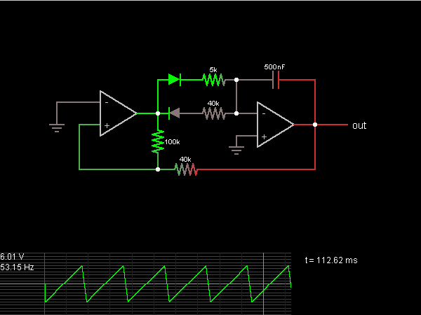
A step sequence can be applied that triggers every other step, allowing the activated steps to rise with each activation. This Low-Frequency Oscillator (LFO) can then be used to modulate other parameters of the plugin to enhance the sound....
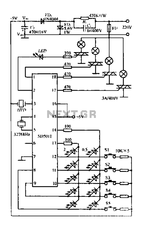
The FIG SD501E is a J tie fan integrated circuit (IC) characterized by progressive timing and three operational modes: strong, medium, and weak. It features three types of output settings and includes an electrical swing mechanism. The device is...
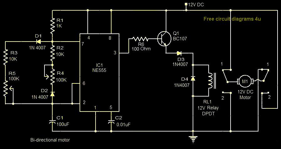
This circuit illustrates a bi-directional motor control circuit utilizing the NE555 integrated circuit (IC). Features include a 12V DC power supply, with the IC employed to control relay RL1. The bi-directional motor control circuit designed with the NE555 IC allows...
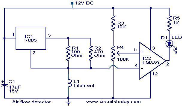
The filament of an incandescent bulb serves as the sensing component of the circuit. When there is no airflow, the resistance of the filament is low. In contrast, when airflow is present, the resistance decreases because the moving air...
The wireless remote control transmitter circuit consists of control buttons S1 to S16, resistors R1 to R3, a capacitor C1, a regulator diode VS, a crystal oscillator BC1, and DTMF encoder integrated circuits IC1 and IC2. The circuit components...

The circuit employs a widely used Sharp IR module (the Vishay module may also be utilized). The pin numbers indicated in the circuit pertain to both the Sharp and Vishay modules. For other modules, it is recommended to consult...