
simple electronic delay detonator

The simple electronic delay detonator circuit is designed to provide a timed delay before activation. The primary components include a diode bridge, which converts alternating current (AC) from the input supply to direct current (DC). This conversion is essential for powering the subsequent components in the circuit.
The power supply capacitor serves as a storage element that smooths out the rectified output from the diode bridge. It ensures a stable voltage supply to the circuit, which is crucial for consistent operation. The RC charging circuit, comprising a resistor (R) and capacitor (C), is responsible for creating the time delay. The time constant of this RC network, defined as τ = R × C, determines how long the capacitor takes to charge to a certain voltage level, which in turn dictates the delay period before the monolithic IC is triggered.
The monolithic IC functions as the control unit for the detonator. Upon reaching the predetermined voltage threshold set by the charged capacitor, the IC activates the output stage, which can trigger a detonator or other load. This design ensures that the circuit can be used in various applications where precise timing is required, such as in controlled detonations or other timing-sensitive operations.
The integration of these components into a hybrid IC module enhances the reliability and compactness of the circuit, making it suitable for deployment in various environments. The careful selection of the resistor and capacitor values allows for customization of the delay time, making this circuit versatile for different applications.Here`s the circuit for a simple electronic delay detonator circuit diagram. The overall circuit is in a hybrid IC module. This is the figure of the circuit; The diode-bridge circuit connected to the input terminals, a power supply capacitor connected to the output of the diode bridge circuit, an RC charging circuit connected in parallel with the capacitor having a predetermined time constant, and a monolithic IC. 🔗 External reference
Related Circuits
This modified Hartley oscillator can be utilized to attract new friends or serve as a replacement doorbell. The modified Hartley oscillator is a type of electronic oscillator that generates a continuous waveform, typically a sine wave, using an LC (inductor-capacitor)...
The BA1404 can be utilized to create a simple and effective FM stereo modulator electronic project. This BA1404 FM stereo modulator device operates within the FM broadcast band (75-108 MHz) and requires only a few common external components. The...
This document discusses the creation of an electronic spy bug circuit using two methods: one involving a wired connection from the transmitter to the receiver, and the other being a completely wireless setup capable of eavesdropping on conversations up...
This circuit utilizes an LM339 quad voltage comparator to create a time delay and manage a high current output at low voltage levels. Approximately 5 amps of current can be achieved using two fresh alkaline D batteries. Three of...
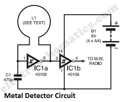
The metal detector circuit presented here exemplifies simplicity while demonstrating effective functionality. It utilizes a single 40106 hex Schmitt inverter IC, a capacitor, a search coil, and batteries. A connection from IC1b pin 4 must be made to a...
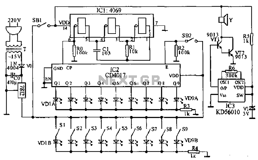
This document presents a principle circuit for electronic games. The main circuit operates in conjunction with the host through the reset button SB2, while the indicators VD1A-VD9A remain off. Prizes, for example, five, are determined by the number of...