
Simple FM Transmitter Bug

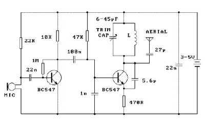
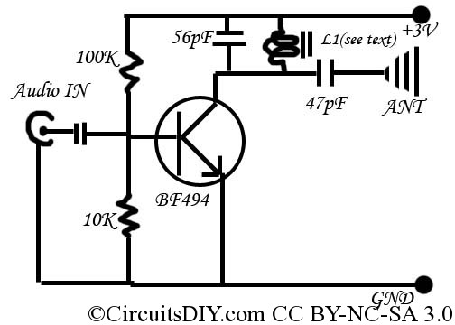
The FM transmitter bug circuit is designed to operate efficiently within the specified parameters. The use of air coils L1 and L2, constructed with five turns of wire, creates an inductor that is crucial for the oscillator's function. The diameter of the coils being approximately 4 mm helps ensure that the inductance is suitable for the desired frequency range. The choice of wire thickness, while flexible, can influence the resistance and thus the overall performance of the transmitter.
The component values are critical for achieving the desired frequency modulation. The resistors R1, R3, and R4, each at 4.7kΩ, help to set the biasing conditions for the transistors T1 and T2, which amplify the audio signal captured by the condenser microphone. The 100kΩ resistor (R2) plays a role in the input impedance, allowing for efficient signal coupling from the microphone to the amplifier stage. The 10kΩ resistor (R5) is used for feedback, which stabilizes the gain of the amplifier.
Capacitors C1 and C2, each rated at 10µF, serve as coupling capacitors, allowing AC signals to pass while blocking DC components. The 1nF capacitors (C3 and C6) are essential for frequency stability and filtering, ensuring that the transmitter operates within the intended frequency band without unwanted oscillations. The trimmer capacitor (C4) provides fine-tuning capability, allowing the user to adjust the transmission frequency precisely to avoid interference with other radio signals.
Overall, this circuit is a compact and effective solution for FM transmission, suitable for various applications, including audio transmission and surveillance. Proper assembly and component selection are essential to ensure reliable operation and optimal performance of the transmitter bug.This is a simple design of a small FM Transmitter Bug that`s perfect for transmitting and eavesdropping purposes. Due to the high sensitivity, even the ticking of the clock to hear. The range is estimated at anything from 50 meters. With a small piece of wire as an antenna to get at least the whole house. L1 and L2 are two equal air pools. They ea ch consist of 5 turns at a diameter of about 4 mm. The thickness of the wire does not matter, 0. 5 mm works perfectly. C4 is the frequency adjustment. Tune an FM radio in an empty area of the FM band and C4 to turn your silence or hear a whistle. From what you can precisely adjust the radio and the transmitter installed in a room somewhere to intercept. Note: Because these transmitter bugs inherently unstable, you better read the short legs of the components keep the circuit mechanically tightly together up.
Also placing a 1 nF capacitor (C6) will benefit stability. R1, R3, R4: 4K7 R2: 100K R5: 10K R6: 270 Ohms C1, C2: 10 uF C3, C6: 1 nF C4: 2-18 pF trimmer C5: 5. 6 pF L1, L2: air puddle windings on May 4 mm in diameter (see text) T1, T2: 547 BC Condenser microphone Original Text: Ook het plaatsen van een 1 nF condensatortje (C6) over de voedingsaanluitingen komt de werking ten goede. 🔗 External reference
Related Circuits
This 2-meter 144 MHz fox hunt transmitter is utilized in amateur competitions where a concealed transmitter is to be "hunted" using primarily homemade receivers. The 2-meter 144 MHz fox hunt transmitter is designed for use in amateur radio competitions, commonly...
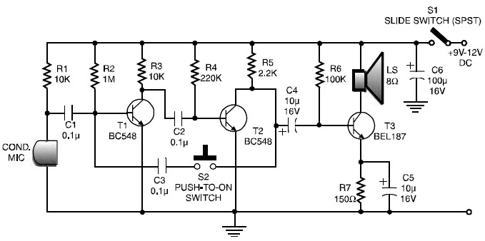
This is a low-cost and simple intercom circuit design that utilizes three transistors. Even a novice can assemble it on a piece of veroboard without difficulty. The intercom circuit is designed to facilitate two-way audio communication between two locations. The...
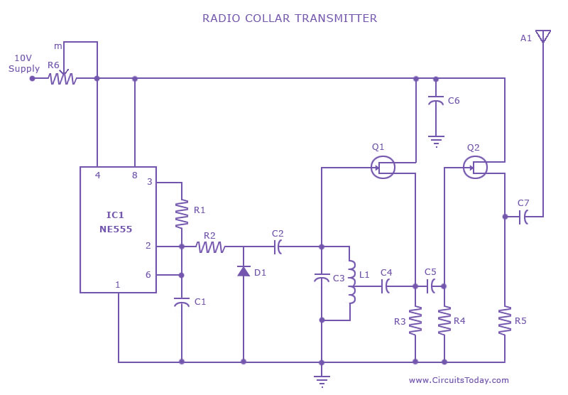
This is a radio transmitter circuit diagram designed for integration into radio collars using the NE 555 integrated circuit. The circuit transmits a pulse in the FM band, specifically between 88 MHz and 105 MHz. The radio transmitter circuit utilizes...
Place the transmitter approximately 10 feet away from an FM radio. Set the radio to a frequency between 89 and 90 MHz. Walk back to the FM transmitter and turn it on. Separate the windings of the coil by...
This is a simple and inexpensive FM transmitter. The circuit operates at a low voltage using a CR2025 3V battery with low current consumption. The total size of this FM transmitter, including the battery but excluding the antenna, is...
A simple USB FM transmitter that can be used to play audio files from an MP3 player or computer on a standard VHF FM radio by connecting it to a USB port. The circuit does not require any coils...