
Radio Collar Transmitter Circuit using NE 555 IC

The radio transmitter circuit utilizes the NE 555 timer IC, which is configured in astable mode to generate a continuous square wave signal. This signal is then modulated to produce frequency modulation (FM) suitable for transmission in the designated frequency range. The circuit typically includes essential components such as resistors, capacitors, and an antenna for efficient signal broadcasting.
In the circuit, the NE 555 timer's frequency output can be adjusted through the selection of resistor and capacitor values, allowing for fine-tuning of the transmission frequency within the FM band. The output from the NE 555 is coupled to a transistor amplifier stage that boosts the signal strength before it is fed to the antenna. This amplification is crucial for ensuring that the signal can be transmitted over a longer distance without significant loss.
The antenna design is also a critical aspect of the circuit, as it must be appropriately sized and configured to match the operating frequency, optimizing the radiation pattern and ensuring efficient transmission. Additionally, power supply considerations are important; the circuit may require a regulated DC voltage source to ensure stable operation of the NE 555 and associated components.
Overall, this radio transmitter circuit is well-suited for applications in which compactness and efficiency are required, such as in radio collars for tracking or communication purposes. Proper implementation of the design will yield reliable performance within the specified frequency range, making it an effective solution for FM transmission needs.This is a radio transmitter circuit diagram suitable for fitting on radio collars using NE 555 IC. he circuit transmits a pulse in the FM between band 88MHz to 105Mhz.. 🔗 External reference
Related Circuits
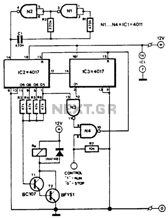
This circuit is designed for a small private telephone installation. The ringing tone sequence consists of 400 ms on, 200 ms off, 400 ms on, and 2 ms off. In the accompanying diagram, N1 and N2 create an oscillator...
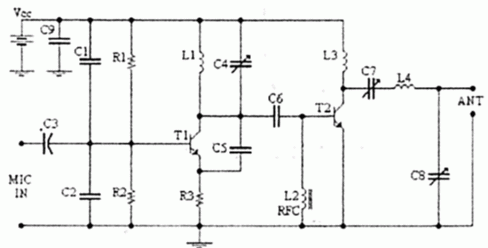
4W FM Transmitter. Technical Characteristics: Stabilized power supply: Vcc = 12~16V. Emission frequency: 88~108MHz. Current consumption: 100~400mA. The 4W FM transmitter is designed to operate within a frequency range of 88 to 108 MHz, which is the standard FM...
This simple aerial booster circuit design could serve as an alternative or a hobby project for creating an aerial booster device for Citizen Band (CB) radio. The aerial booster circuit is designed to enhance the performance of Citizen Band (CB)...
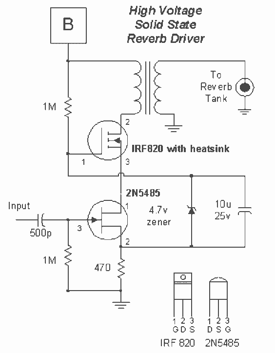
The IRF820 MOSFET has a voltage rating of 500V; it should work well in preamp stages of most tube amps. The 100-ohm resistor is there to suppress H.F. oscillations. If the IRF820 is physically close to the 12AX7 plate,...
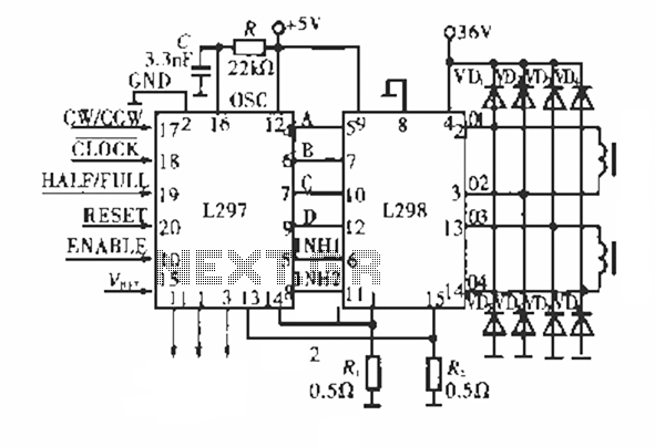
The circuit operates using a dedicated stepping motor controller, the L297. Pin 17 (CW/CCW) is utilized to control the rotation direction of the stepper motor. Pin 18 (CLOCK) regulates the speed of the stepper motor, while pin 19 (HALF/FULL)...

The AD650 is a voltage-to-frequency (V/F) and frequency-to-voltage (F/V) converter that offers high-frequency operation and low nonlinearity, features that were previously unavailable in a monolithic form. Its inherent monotonicity in the V/F transfer function makes the AD650 suitable for...