
Simple Headlight Reminders circuit
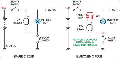
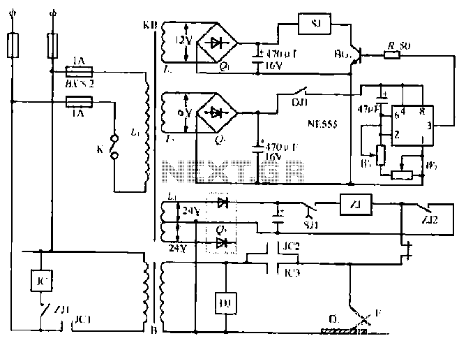
The two headlight reminder circuits illustrate a straightforward approach to preventing battery drain by providing an auditory alert when vehicle lights are inadvertently left on. The initial circuit design utilizes a 12V piezo buzzer, which is a compact and efficient sound-producing device. This buzzer is wired in such a way that it becomes active when the door switch is engaged. The simplicity of this system makes it accessible for installation in various vehicles, requiring minimal components and tools.
In the improved circuit, the addition of a 1000µF capacitor plays a crucial role in controlling the buzzer's operation. When the door is opened, the capacitor begins to charge, allowing the buzzer to emit a short sound rather than a continuous tone. This design modification significantly enhances user experience by reducing annoyance while still providing an effective reminder. The 100kΩ resistor is strategically placed in parallel with the buzzer to ensure that the capacitor discharges when the lights are turned off, resetting the system for future use.
Overall, these circuits exemplify practical engineering solutions to common automotive issues, balancing simplicity with functionality. The incorporation of basic electronic components, such as a piezo buzzer, capacitor, and resistor, demonstrates how effective designs can be achieved without complex circuitry, making them suitable for a wide range of applications in automotive electronics.These two headlight reminder circuits are easy to install and operate on the KISS (Keep It Simple Stupid) principle. The simple circuit involves adding just a 12V piezo buzzer between the lights circuit and a door switch.
The buzzer sounds if the lights are left on and you open a door. The disadvantage of this simple circuit is that it`s annoying to have the buzzer sound continuously if you want to leave the door open while the lights are on. The improved circuit overcomes that problem by adding a 1000µF capacitor and a parallel 100kO resistor in series with the buzzer.
Now, when a door is opened, the buzzer gives a brief burst of sound only, while the 1000µF capacitor charges. The 100kO resistor discharges the capacitor when the lights are switched off.. 🔗 External reference
Related Circuits
The 27MHz crystal oscillator circuit is illustrated in the figure. Resistors R1, R2, and R3 serve as biasing resistors, while capacitor C6 functions as a bypass capacitor. The voltage division circuit consists of capacitors C1, C3, C4, and C2,...
This page provides basic information about voltage comparator integrated circuits and is to act as reference material for other circuits. The circuits shown are based on the LM339 Quad Voltage Comparator chip or the LM393 Dual Voltage Comparator chip....
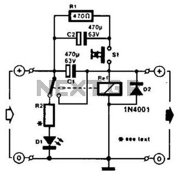
A method of adding overload protection to a power supply using a relay is shown. In each circuit, the relay must be reset by a momentary switch using a charge on capacitor C2. This prevents overload if the short...
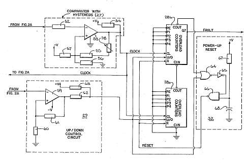
This motor overload circuit allows for short-term overdriving of a system, which is dependent on heat buildup. An overload detection circuit safeguards the motor against currents exceeding the rated current for specific exposure durations. The permissible exposure times are...
The NE555 timer circuit functions as a vibration generator. The input pin 3 produces pulse frequencies ranging from 5 to 20 Hz. The circuit includes a fan that operates within a bamboo enclosure. The barrel section is designed to...

The image illustrates a circuit that utilizes a linear potentiometer (or linear Hall element) to control the PWM generation for two chassis drive motors in a gamepad or joystick used in model aircraft. J1 represents the handle of the...
Warning: include(partials/cookie-banner.php): Failed to open stream: Permission denied in /var/www/html/nextgr/view-circuit.php on line 713
Warning: include(): Failed opening 'partials/cookie-banner.php' for inclusion (include_path='.:/usr/share/php') in /var/www/html/nextgr/view-circuit.php on line 713