
Simple humidity detector

The piezoelectric speaker may be substituted with an electromechanical relay, which can activate additional external devices such as a horn, lamp, or any other apparatus capable of providing a noticeable alert. It is important to note that since the current driving the relay coil is pulsed (DC = 50%), the voltage must be lower than the voltage of the humidity detector. For instance, if the supply voltage of the detector is 9 V, the relay should operate effectively at 6 V. The circuit typically consumes around 4-5 mA, but this can increase to 40 mA when the relay contacts are engaged. The supply voltage can range from 3 to 15 V; however, when operating at the lower end of the voltage range, the relay should not exceed 8 V. If the circuit proves to be overly sensitive during operation, the resistance value of R2 can be decreased.
This circuit utilizes a flip-flop configuration for memory retention, allowing it to maintain its output state until the humidity condition changes. The integrated circuits IC1a and IC1b serve as the core logic components, processing the input from the humidity sensor. The oscillator IC1c generates a signal that drives the piezoelectric speaker, providing auditory feedback when the humidity exceeds the set threshold.
The design allows for flexibility in the components used; for example, the piezoelectric speaker can be replaced with a relay that can control higher power devices. This adaptability is beneficial for various applications, from simple alert systems to more complex automation setups.
The current consumption characteristics highlight the efficiency of the circuit, enabling it to operate on a relatively low power supply while still providing sufficient current to control a relay. This feature makes it suitable for battery-operated devices or applications where energy conservation is critical.
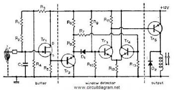
In summary, this circuit effectively monitors humidity levels and activates a corresponding alert mechanism, with options for customization based on specific application requirements. Adjustments to component values, such as R2, allow for fine-tuning of sensitivity, ensuring optimal performance in diverse environmental conditions.The main (and only) job of this circuit is to activate a buzzer or a relay, each time the level of humidity takes a specific value. Main stage is a memory based on a flip-flop consisting of gates and IC1a IC1 b. The output of this step activates an oscillator (IC1c), which in turn leads to a piezoelectric speaker.
At the start of operation of the circuit, the flip-flop is driven to logical '0' or through the C1 or through C2. From the moment you excited, the reintroduction of the peace achieved through the switch S1, which however is insufficient if the sensor 82 continues to be wet.
The piezoelectric speaker can easily be replaced by a ilektronomo which in turn activates another external power device, such as a horn, a lamp or anything else is able to provide a distinctive indication. For the relay should note that because the current that drives the coil is pulsed (DC = 50%), the voltage should be less dp 'is the voltage of the detector.
If for example supply voltage of the latter is 9 n, then the relay is good to work at 6 V. The current circuit absorbs the rest of the order of 4-5 mA, but increased to 40 mA if the tow relay contacts. The supply voltage can be between 3 and 15 n, but if you use the lower limit relay is limited to 8 V.
If during the use of the circuit proved highly sensitive, you can reduce. the value of R2.
Related Circuits
Flame, gas, and smoke detector for fire alarm. This circuit can be combined with an alarm circuit. The output will be a relay that activates and deactivates the alarm. The diagram above illustrates the flame detector. The circuit diagrams...
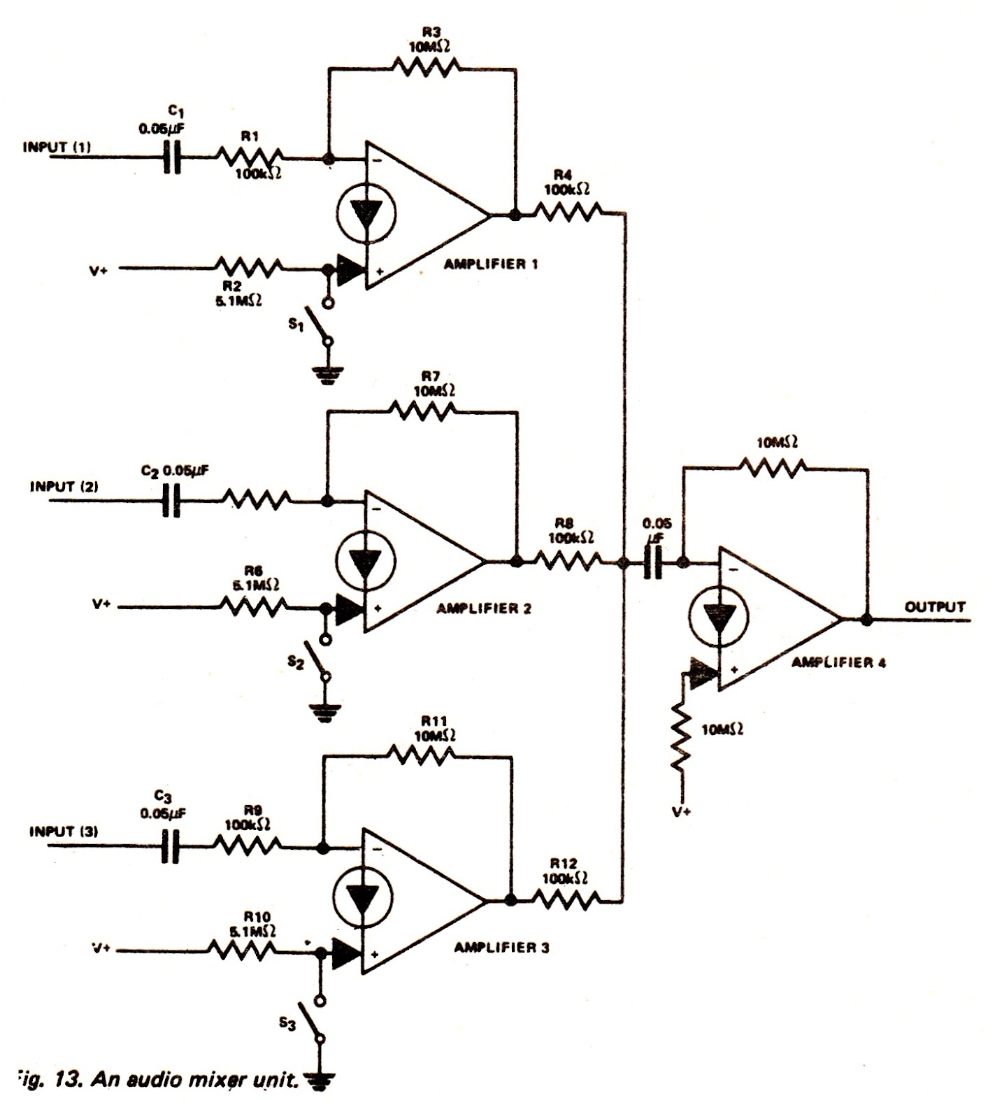
The amplifiers of an LM3900N device can be utilized to create an audio mixer unit that allows for the combination of three separate audio signals into a single composite output. The audio mixer circuit provided operates with a single...
At the core of this circuit is a precision integrated temperature sensor, the LM35 (IC1), which provides a linear and directly proportional output related to temperature measurements. The LM35 temperature sensor is a well-known device used for temperature sensing applications....
This relatively simple mixer was designed for three dynamic microphones, but can be re-designed for more or less. Level and tone controls are available to tailor the sound to your needs. More: R1-R3 are level controls. R9 and R11...
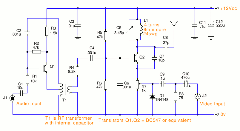
This is a small TV transmitter circuit that transmits in VHF, utilizing negative sound modulation and PAL video modulation. It is suitable for countries that use the B and G system. T1 refers to a type of transformer. The...
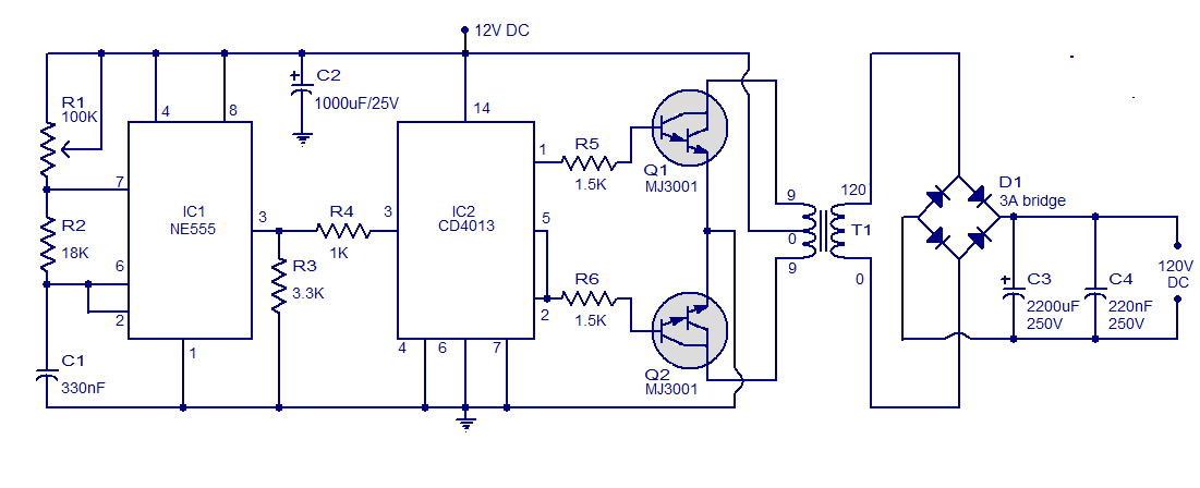
This is a simple circuit designed to convert 12V DC to 120V DC. The circuit comprises two main phases: the inverter stage and the rectifier and filter stage. The NE555 integrated circuit (IC1) is configured as an astable multivibrator,...