
Flame gas and smoke detector

Components List:
- R1, R2, R3 = 22M Ohms
- R4 = 2.2M Ohms
- C1 = 0.47uF/250V Mylar capacitors
- D1 = 1N914, NTE519, or other small signal diodes
- Q1 = 2N3904, NTE123AP
- Q2 = 2N3906, NTE159
- Q3 = IRF510, NTE2382, MosFet
This circuit is a simple and easy-to-build metal detector circuit based on a CS209A IC. It provides impressive results while drawing minimal current from a 9-volt battery. Although it performs well on a workbench, its effectiveness in outdoor metal detection may vary. Nevertheless, it is an excellent circuit for sensing applications. Additionally, an ultrasonic motion detector circuit is included, which claims to have high sensitivity to movement. Even slight air movements (such as hot air rising or wind blowing) can trigger it when the trimpot is adjusted to its most sensitive setting. The transmitter emits a steady ultrasonic tone at 40kHz, creating a specific wavelength for detection.
The flame, gas, and smoke detector circuit integrates various sensing technologies to provide comprehensive fire safety solutions. The flame detector utilizes infrared or ultraviolet sensors to identify the presence of flames, while the gas detector typically employs semiconductor sensors to detect combustible gases. The smoke detector uses ionization or photoelectric sensors to identify smoke particles in the air.
In conjunction with the alarm circuit, the relay output can be configured to trigger various alarm systems, including sirens or visual indicators, ensuring prompt notification of potential fire hazards. The use of a 12V power supply allows for flexibility in power sourcing, accommodating various applications and installations.
The heat detector circuit, which integrates a siren, enhances the overall safety mechanism by providing an additional layer of detection, specifically targeting heat increases indicative of fire. The complementary transistor pair effectively amplifies the signal from the heat sensor, allowing for reliable activation of the alarm system.
The tone detector circuits add versatility, enabling sound-activated operations that can be beneficial in automated systems, such as robotics. The inclusion of a microcontroller in these circuits facilitates advanced functionalities, such as programmable responses to specific sound frequencies.
Overall, these circuits represent a robust approach to fire detection and alarm systems, with straightforward designs that can be easily implemented in various environments. The component selection ensures reliability and effectiveness in detecting potential fire hazards, contributing to enhanced safety measures.Flame, gas and smoke detector for fire alarm. You can combine this circuit with alarm circuit. The output will be the relay which switch on and switch off the alarm. The above scheme diagram is the diagram of flame detector. The circuit diagram for gas detector and smoke detector separated in different circuit design diagram which can be download ed from the provided link. All of schematic diagrams (flame detector, gas detector and smoke detector) are quite simple and easy to built. It uses 12V power supply to work, you may use batteries or accumulator or DC power supply for powering the circuit.
Tags: Alarm, circuit diagram of smoke detector, fire, Flame, flame detector circuit, gas, gas detector circuit, gas sensor circuit diagram, smoke detector, smoke detector circuit diagram, This is the diagram of heat detector circuit which already integrated with siren circuit in the output. This circuit applies a complementary pair comprising NPN metallic transistor T1 (BC109) and PNP germanium transistor T2 (AC188) to detect heat (because of outbreak of fire, for example) in the area and activate a siren/alarm.
The collector of. The following circuit diagrams are tone detector circuit diagrams which also known as sound activated switch circuit. Actually, these circuits use microntroller for switching because the circuits were designed for robot start up activation.
But you can build switching module using relay. Tone Detector diagram 1 Tone Detector diagram 2 Tone Detector diagram 3 Tone. This circuit is used to detect whether your phone line is active or not. Components List: R1, R2, R3 = 22M Ohms R4 = 2. 2M Ohms C1 = 0. 47uF/250V Mylar caps D1 = 1N914, NTE519, or other small signal diode Q1 = 2N3904, NTE123AP Q2 = 2N3906, NTE159 Q3 = IRF510, NTE2382, MosFet This kind of circuit. This is a very simple and easy build metal detector circuit, built based on a CS209A IC. The circuit will give surprising results and draws extremely small current from a 9 volt battery. It worked great on the Bench, But not so good outside for common metal detecting. But Definately a great circuit for sensing. This is a ultrasonic motion detector (or movement detector) circuit. The circuit claimed has a high movement sensitivity. Even air moving (hot air rising, wind blowing) will trigger it when the trimpot is set near the most sensitive position.
The transmitter sends out a steady ultrasonic tone at 40kHz. At this frequency the wavelength is. 🔗 External reference
Related Circuits

To determine whether it is freezing, it is necessary to measure the temperature accurately using a reliable temperature sensor. The LM35CZ, which operates between -40 to 110 °C, has been chosen for this purpose. This sensor generates an output...
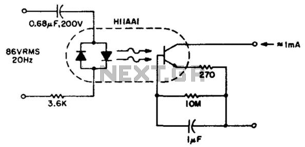
This circuit detects the approximately 20-Hz, 86-Vrms ring signal on telephone lines and initiates action in an electrically isolated circuit. Typical applications include automatic answering equipment, interconnect/interface systems, and key systems. The detector is designed to be simple and...
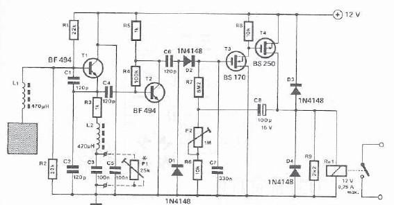
A simple proximity detector can be created using this electronic circuit. This circuit responds to the presence of a conductive object within a specific range. The sensitivity of the circuit can be adjusted with potentiometer P1 to achieve the...

This circuit is designed for sound detection and generates an output signal when sound is detected. This output can trigger another circuit that activates an alarm, making it suitable for security applications. The circuit employs a condenser microphone to...
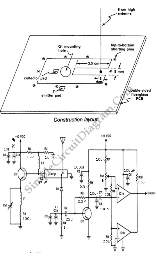
The UHF motion detector operates on the Doppler radar principle. An oscillating signal is generated by the oscillator (Q1), and a portion of this energy is reflected back. The UHF motion detector employs the Doppler radar principle to detect motion...

This is a linear frequency modulation (FM) detector circuit. This circuit is commonly utilized in telemetry applications and a wide range of analog communication systems. The primary component of this circuit... The linear FM detector circuit is designed to demodulate...