
Simple TV Transmitter Circuit
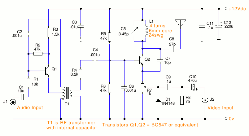
The small TV transmitter circuit operates in the VHF band, specifically designed for negative sound modulation and PAL video modulation, making it suitable for regions utilizing the B and G television system. The circuit's core components include T1, an intermediate frequency (IF) transformer, which plays a critical role in signal processing. This transformer is commonly used in FM tuners and is typically characterized by a green casing and a capacitor positioned at its base.
Capacitance values are essential for the circuit's functionality. C1 is identified as a non-polarized capacitor with a capacitance of 10 µF and is typically a tantalum type. The capacitors labeled C5 and C8 contain the letter "P," indicating their capacitance is measured in picofarads, a common unit for ceramic capacitors.
The circuit design includes an audio section, with R8 connecting from the transformer to C4. However, this section can be bypassed in favor of a dedicated audio amplifier, which can be integrated into the overall system. The output from the pre-amplifier can be linked to C4, facilitating the connection of a speaker while ensuring proper grounding.
The choice of antenna is crucial for effective transmission. An appropriate antenna type should be selected based on the transmitter's specifications and the desired range, which is yet to be defined.
For those interested in constructing a similar transmitter, detailed circuit design calculations for a low-cost UHF audio/video/data transmitter and receiver capable of achieving a range of 3-5 km would be beneficial. This information is pivotal for successful project execution and optimization of system performance.This is a small tv transmitter circuit wich trasmittes in VHF, negative sound modulation and PAL video modulation. It is suitable in countries where the B and G system is used. T1 which type of transformer. what is C1 value. what means of letter P which in in capacitors like C5 and C8. which type of antina will be best for this and how much is its range. T1 which type of transformer. what is C1 value. what means of letter P which in in capacitors like C5 and C8. which type of antina will be best for this and how much is its range. T1 which type of transformer. what is C1 value. what means of letter P which in in capacitors like C5 and C8. which type of antina will be best for this and how much is its range. T1 is an IF transformer as seen in FM tuner this is a color green IF with capacitor at the bottom, p means picofarad a unit for ceramic capacitor, pls look at the diagram C1 symbol is non polarized capacitor, 10uF value is a tantalum capacitor R8 Comes from Transformer going to C4, forget that whole side of the circuit because it just deals with Audio, you can build your own Audio amp and couple it in to the Oscilator or final stage through C4 ²s Capacitor, just wire your Headphone out from Pre-Amp to C4, and hook Ground, So Speaker + Y I am constructing a TV Transmitter my self, different design. Good Luck, and don`t be asking me a whole load of questions, because I`m just passing by this site. I will be interested if you can supply me with details of circuit design calculations of a low cost, UHF, 3-5 km, audio/video/data transmitter and receiver, for i am to design and construct one for my project.
thanks 🔗 External reference
Related Circuits
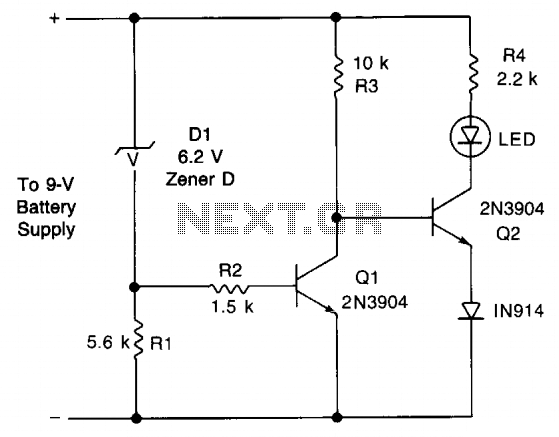
This circuit provides an early warning for battery discharge. A Zener diode (D1) is selected to indicate when the voltage falls below 9 V. If the supply voltage drops below 7 V, D1 will stop conducting, which will cause...

Basic features include an internal 512k-bit EEPROM, allowing for continuous recording and playback at any time, with long-term retention of voice data after power loss. The voice recording time is 20 seconds, and it supports segmented recording and playback....
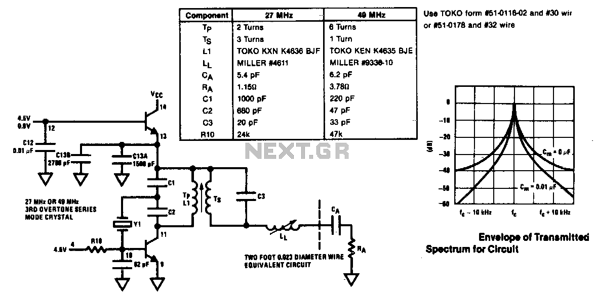
The modulator and oscillator comprise two NPN transistors. The base of the modulator transistor is powered by a bidirectional current source, with the voltage range for the high condition restricted by a saturating PNP collector connected to the pin...
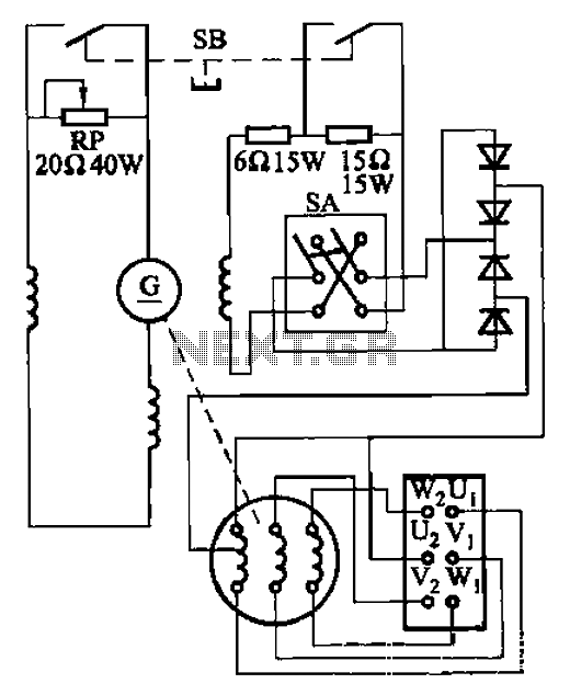
The AX3-300-2 DC arc welding machine circuit is part of the AX, AX1, AX3, and AR series of rotary DC arc welding machines. These machines share a similar structural design, featuring a three-integral unit configuration that combines an inverter...
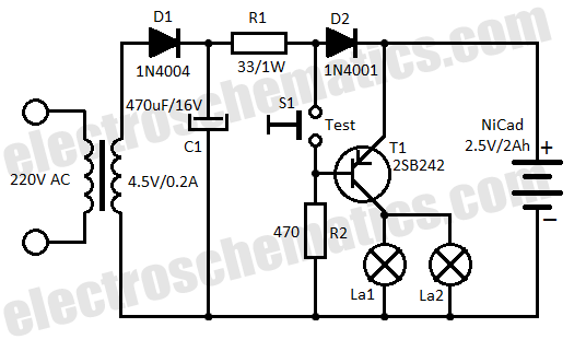
This low-cost automatic emergency lighting circuit activates a lamp during power failures. It is powered by a NiCad battery that is charged by the mains. The automatic emergency lighting circuit is designed to provide illumination during unexpected power outages. The...
This source is selected by pressing a momentary-contact pushbutton switch (SI). Switch SI is connected to the trigger of a 555 oscillator/timer (U1) configured as a monostable multivibrator, which generates one short output pulse for each press of SI....