
Simple Hybrid Audio Amplifier

The amplifier circuit described combines the benefits of both valve and solid-state technologies, resulting in a hybrid amplifier that offers unique audio characteristics. The use of a valve in the pre-amplifier stage contributes warmth and richness to the sound, while the MOSFET output stage provides efficiency and power handling capabilities. The design emphasizes the importance of feedback in achieving a flat frequency response, which is critical for high-fidelity audio applications.
The choice of components plays a significant role in the performance of the amplifier. The ECC83 valve, known for its low noise and high gain, is a suitable choice for the pre-amplifier stage, while the MOSFET's ability to handle high currents makes it ideal for the output stage. The careful selection of coupling capacitors ensures minimal signal degradation, preserving audio quality.
Thermal management is a critical consideration in this design, particularly due to the Class A operation of the output stage, which results in higher power dissipation. The recommended heatsink specifications ensure that the MOSFET operates within safe temperature limits, thus enhancing reliability and longevity.
The inductor design is crucial for low-frequency performance. By utilizing an iron core with an air gap, the circuit can effectively handle large DC currents without saturation, which is essential for accurate bass reproduction. The modification process for the transformer into an inductor illustrates the adaptability of the design and encourages users to engage in hands-on experimentation.
Overall, this amplifier circuit serves as a compelling project for electronics enthusiasts, offering opportunities for customization and improvement while delivering high-quality audio performance.The debate still goes on as to which are better, valves or transistors. We don`t intend to get involved in that argument here. But if you can`t make your mind up, you should try out this simple amplifier. This amplifier uses a valve as a pre-amplifier and a MOSFET in the output stage. The strong negative feedback makes the frequency response as fl at as a pancake. In the prototype of the amplifier we`ve also tried a few alternative components. For example, the BUZ11 can be replaced by an IRFZ34N and an ECC83 can be used instead of the ECC88. In that case the anode voltage should be reduced slightly to 155 V. The ECC83 (or its US equivalent the 12AX7) requires 2 x 6. 3 V for the filament supply and there is no screen between the two triodes, normally connected to pin 9. This pin is now connected to the common of the two filaments. The filaments are connected to ground via R5. If you`re keeping an eye on the quality, you should at least use MKT types for coupling capacitors C1, C4 and C7.
Better still are MKP capacitors. For C8 you should have a look at Panasonic`s range of audio grade electrolytics. P1 is used to set the amount of negative feedback. The larger the negative feedback is, the flatter the frequency response will be, but the smaller the overall gain becomes. With P2 you can set the quiescent current through T2. We have chosen a fairly high current of 1. 3 A, making the output stage work in Class A mode. This does generate a relatively large amount of heat, so you should use a large heatsink for T2 with a thermal coefficient of 1 K/W or better.
For L1 we connected two secondary windings in series from a 2x18V/225 VA toroidal transformer. The resulting inductance of 150 mH was quite a bit more than the recommended 50 mH. However, with an output power of 1 W the amplifier had difficulty reproducing signals below 160 Hz. The distortion rose to as much as 9% for a signal of 20 Hz at 100 mW. To properly reproduce low-frequency signals the amplifier needs a much larger coil with an iron core and an air gap. This prevents the core from saturating when a large DC current flows through the coil. Such a core may be found in obsolete equipment, such as old video recorders. A suitable core consists of welded E and I sections. These transformers can be converted to the required inductor as follows: cut through the welding, remove the windings, add 250 to 300 windings of 0.
8 mm enamelled copper wire, firmly fix the E and I sections back together with a piece of paper in between as isolation. The concepts used in this circuit lend themselves very well to some experimentation. The number of supply voltages can be a bit of a problem to start with. For this reason we have designed a power supply especially for use with this amplifier (Quad power supply for hybrid amp).
This can of course just as easily be used with other amplifiers. The supply uses a cascade stage to output an unstabilised voltage of 170 V for the SRPP (single rail push pull) stage (V1). During initial measurements we found that the ripple on this supply was responsible for a severe hum at the output of the amplifier.
To get round this problem we designed a separate voltage regulator (High-voltage regulator with short circuit protection), which can cope with these high voltages. If you use a separate transformer for the filament supply you can try and see if the circuit works without R5.
During the testing we used a DC voltage for the filament supply. Although you may not suspect it from the test measurements (see table), this amplifier doesn`t sound bad. In fact, it is easily better than many consumer amplifiers. The output power is fairly limited, but is still enough to let your neighbours enjoy the music as well.
It is possible to make the amplifier more powerful, in which case we recommend that you use more than one MOSFET in the output stage. The inductor also needs to be made beefier. Since this is 🔗 External reference
Related Circuits
This is the circuit of a 500 watt linear amplifier, based upon a design by Frits Geerligs, PA0FRI, who has his own homepage at http://home.planet.nl/~fhvgeerligs. The circuit uses four PL519 TV line output valves in a very simple circuit...
A circuit breaker is an electronic device that functions to protect an electrical circuit from hazards or damage caused by overloads or short circuits. A circuit breaker operates by automatically interrupting the flow of electricity when it detects an...
This tester can be used to check the polarity of any power source, and is therefore very useful when installing automotive equipment, alarm systems or anything else you can think of. Because this circuit is so simple and cheap,...
This circuit amplifies voice audio in the frequency range of 50 to 10,000 Hz with minimal distortion and is capable of driving a low impedance load of up to 16 ohms. It operates on a DC voltage of 6...
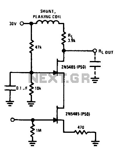
The FET cascode video amplifier exhibits very low input loading and minimizes feedback to nearly zero. The 2N5485 transistor is utilized due to its low capacitance and high transconductance (YfS). Additionally, the bandwidth of this amplifier is constrained by...
The TDA2040 is a monolithic integrated circuit housed in a Pentawatt package, designed for use as an audio class AB amplifier. It typically delivers an output power of 22W (with a distortion factor of 0.5%) at a supply voltage...