
Simple Polarity Tester

The polarity tester circuit typically consists of a few basic components: a power source, a diode, an LED indicator, and resistors. The circuit is designed to be connected to the power source under test, which can be a battery or any DC power supply.
When the circuit is connected, the diode allows current to flow in one direction only, which is determined by the polarity of the power source. If the positive terminal of the power source is connected to the anode of the diode and the negative terminal to the cathode, the diode will conduct, allowing current to flow through to the LED indicator. The LED will light up, indicating that the polarity is correct.
Conversely, if the connections are reversed, the diode will block the current flow, preventing the LED from lighting up. This simple yet effective design provides a clear visual indication of the power source's polarity.
The inclusion of a resistor in series with the LED is essential to limit the current flowing through the LED, preventing damage from excessive current. The resistor value can be calculated based on the forward voltage of the LED and the supply voltage to ensure optimal performance.
Due to the simplicity of this circuit, it is cost-effective and can be easily built or repaired, making it a practical tool for automotive and electronic applications. The robustness of the design also allows it to withstand occasional overvoltage situations without significant damage, ensuring longevity and reliability in various testing scenarios.This tester can be used to check the polarity of any power source, and is therefore very useful when installing automotive equipment, alarm systems or anything else you can think of. Because this circuit is so simple and cheap, even frying one with an over voltage is not a big deal. 🔗 External reference
Related Circuits
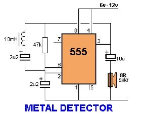
Assemble the circuit on a perfboard or PCB, excluding the inductor. Attach two long wires in place of the inductor. Use a long rod and position the inductor. The circuit assembly begins with the preparation of a perfboard or printed circuit...
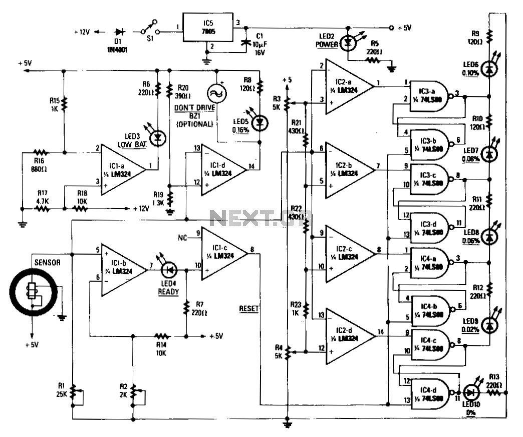
When power is applied to the circuit, the heater coil in the sensor is energized by the 5-V output of IC5, a 7805 voltage regulator. Breathing into the sensor with alcohol on one's breath will lower the sensor's resistance;...
Tro telephones can be utilized as an intercom through the implementation of this circuit. Traditional rotary phones, particularly those that are non-electronic, may be the most effective for this purpose. Additionally, this method can also power handsets alone. The circuit...

To create a telephone ring monitor, it is sufficient to connect a resistor in series with a bulb and plug it into a main outlet. The resistance value of this resistor may vary depending on the type of bulb...

This circuit is utilized for proximity detection and touch-controlled switching. When a finger approaches the sensor, it generates a capacitance to ground with a value ranging from 30 to 100 pF. Components involved include a resistor, capacitor, diode, and...
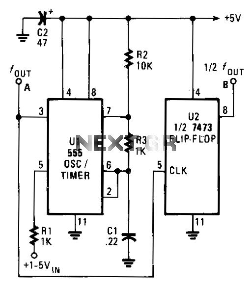
The output frequency of the voltage-controlled oscillator (VCO), U1, varies inversely with the input voltage. With a 1 V input, the oscillator output frequency is approximately 1500 Hz; with a 5 V input, the output frequency decreases to around...