
Simple Car Circuit Breaker Schematic Diagram

A circuit breaker operates by automatically interrupting the flow of electricity when it detects an abnormal condition, such as excessive current or a short circuit. The device is designed to safeguard electrical systems and prevent potential hazards, such as electrical fires or equipment damage.
In general, circuit breakers can be classified into two main types: thermal and magnetic. Thermal circuit breakers use a bimetallic strip that bends under excessive heat generated by high current, triggering the opening of the circuit. Magnetic circuit breakers, on the other hand, utilize an electromagnetic coil that generates a magnetic field when current exceeds a predetermined threshold, pulling a lever to disconnect the circuit.
The schematic representation of a circuit breaker typically includes the following components: the input terminal, output terminal, the bimetallic strip or electromagnetic coil, a mechanical latch, and a reset mechanism. The input terminal connects to the power source, while the output terminal connects to the load. The bimetallic strip or coil is positioned in such a way that it can effectively respond to current changes. The mechanical latch holds the circuit closed until an overload condition is detected, at which point it releases, opening the circuit.
In addition to the basic functionality, modern circuit breakers may also include features such as adjustable trip settings, LED indicators for status monitoring, and integration with smart home systems for remote control and monitoring. These enhancements improve the usability and effectiveness of circuit breakers in contemporary electrical systems.
Overall, circuit breakers are crucial components in electrical engineering, providing essential protection and enhancing the safety of electrical installations.Circuit breaker is an electronic devices which function is to protect an electrical circuit from hazard/damage due to overload or short circuit. This car.. 🔗 External reference
Related Circuits
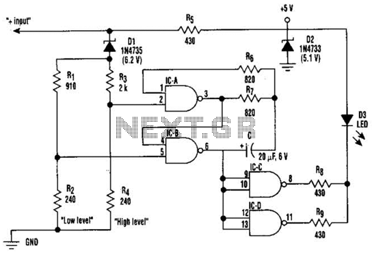
This circuit displays three voltage levels: normal (11 to 15 V), high (greater than 15 V), and low (below 11 V). When the voltage is low, the LED illuminates steadily. In the normal voltage range, the LED remains off....
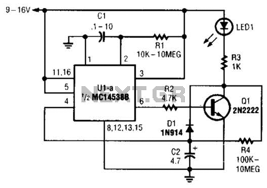
When power is first applied to the circuit, capacitor C2 begins to charge through LED1, resistor R3, and resistor R4. When the voltage across C2 reaches the input trigger level of operational amplifier U1, the output at pin 6...
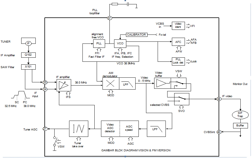
This section is designed to amplify the signal until it reaches the required level. The IF amplifier is equipped with an Automatic Gain Controller (AGC) that regulates the amplification to ensure a constant amplitude output for the video. The...
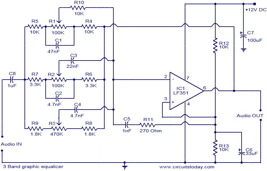
This document presents the circuit diagram of a simple three-band graphic equalizer that utilizes a single integrated circuit (IC) and a few additional components. The IC employed in this design is the LF351, which is a wide bandwidth single...
555 low power timing circuit diagram. The diagram is from the technical information of Chinaicmart. For more detailed information about the circuit diagram. The 555 timer IC is widely utilized in various applications due to its versatility and ease of...
The simple pressure sensor alarm is constructed using a few inexpensive and readily available components. The operation of this circuit is straightforward and self-explanatory. When powered by a 9V compact battery, the active piezo sounder at the output of...