
Simple Intercom Circuit
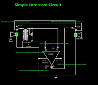
The intercom circuit operates using the LM380 audio power amplifier, which is designed to provide sufficient audio output for communication between two parties. The circuit configuration includes a switch that toggles between two states: talk and listen. In the talk position, the microphone captures the speaker's voice and amplifies it through the LM380, allowing the left speaker to transmit audio to the listener. The listener's speaker receives this amplified signal, enabling clear communication.
When the listener wants to respond, the switch must be toggled to the talk position, allowing the listener to speak into their microphone while the left speaker becomes the listener. This requires both users to actively manage the switch to facilitate a two-way conversation.
The grounding of pins 3, 4, 5, 10, 11, and 12 is crucial for the stability and performance of the LM380, ensuring that the amplifier operates within its specified parameters. Proper grounding minimizes noise and interference, which is essential for maintaining audio clarity during conversations.
The circuit design may include additional components such as capacitors for filtering and resistors for setting gain levels, which contribute to the overall functionality and performance of the intercom system. Careful attention to these details will enhance the user experience by improving sound quality and reliability in communication.This is simple intercom circuit. Here I have used common Ic LM380. Now the switch is in the talk position for the speaker on the left, And the other persons position is listening position. If other one wants to speak The switch must be change to another position. (Both users should do that). Pins 3, 4, 5, 10, 11, 12 are grounded. 🔗 External reference
Related Circuits
A rain sensor alarm circuit is a useful device for alerting when rainfall occurs. The rain detector circuit presented is straightforward, utilizing only three components while maintaining high sensitivity to detect rain or moisture. The sensor can be constructed...
The circuit of a loop sensor-based simple security alarm is described here. The sensor loop consists of a short length of thin enamelled copper wire. The loop sensor security alarm operates on the principle of detecting interruptions in the circuit...
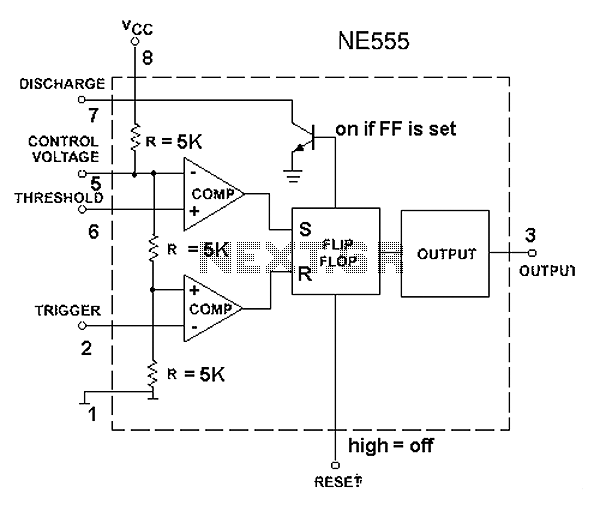
The 555 timer circuit, regardless of the manufacturer, has a consistent internal structure and performance. Various manufacturers produce different models of the 555 timer, including MC555, CA555, XR555, LM555, as well as domestic models like SL555, FX555, and 5G1555....
A simple audio amplifier with a 10 Vpp output designed for use with the AD633 ring modulation chip. The datasheet for the chip is available, and the circuit will utilize the XR2206 function generator IC for the modulation input....
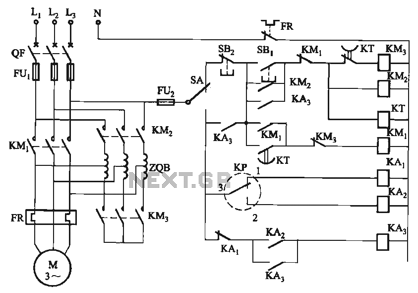
The circuit utilizes a motor auto-voltage transformer for starting. The motor auto-voltage transformer start circuit is designed to provide a controlled method for initiating the operation of an electric motor. This type of circuit is particularly beneficial in applications where...

This circuit is a Phase-Locked Loop (PLL) system designed for use as an FM demodulator. The output of the Voltage-Controlled Oscillator (VCO) follows the FM signal, with the input voltage to the VCO being proportional to its output frequency....