
Telecom Converter Circuit

The circuit utilizes the National Semiconductor LM2575, which is a step-down (buck) switching regulator designed to convert a higher input voltage to a lower output voltage efficiently. In this application, the circuit is configured to provide a stable output of +5 V with a maximum current of 1 A, drawing power from a -48 V supply typically found in telecommunication systems.
The LM2575 operates by rapidly switching the input voltage on and off, controlling the energy delivered to the output through an inductor. This process minimizes energy loss, making it an efficient solution for applications where power conservation is critical. The switching frequency is typically set at 52 kHz, allowing for a balance between efficiency and component size.
Key components in the circuit include the LM2575 regulator itself, an inductor that stores energy during the ON phase, a diode that allows current to flow to the output when the regulator is OFF, and output capacitors that smooth the voltage to provide a stable output. The feedback mechanism ensures that the output voltage remains constant despite variations in load current or input voltage.
Additional features of the LM2575 include thermal protection, which prevents overheating, and the ability to operate with input voltages as low as -40 V and as high as -60 V, making it versatile for various applications. The circuit design must also account for proper layout and grounding to minimize noise and ensure stable operation.
Overall, this circuit provides a reliable solution for converting a -48 V supply to a +5 V output, suitable for powering electronic devices in telecommunication environments. The circuit supplies 1 A at +5 V from the -48-V supply commonly used in telephone equipment. The National Semiconductor LM2575 is a simple switching regulator.
Related Circuits
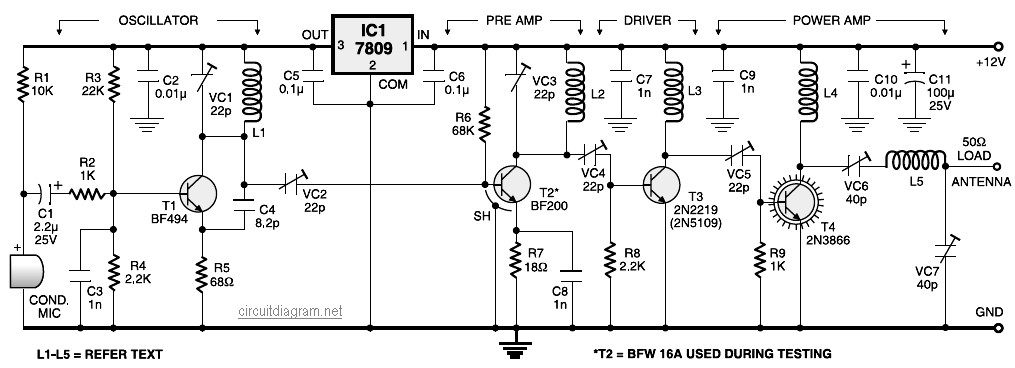
A four-stage FM transmitter circuit diagram utilizes four radio frequency stages: a VHF oscillator designed around the BF494 transistor (T1), a preamplifier based on the BF200 transistor (T2), a driver built with the 2N2219 transistor (T3), and a power...
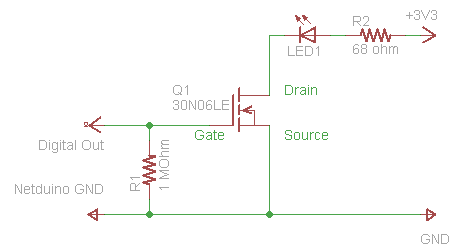
The process of driving an LED involves using a Power MOSFET to control the LED's state (On and Off) via a digital signal. This guide provides a step-by-step approach to wiring the circuit on a breadboard, which serves as...
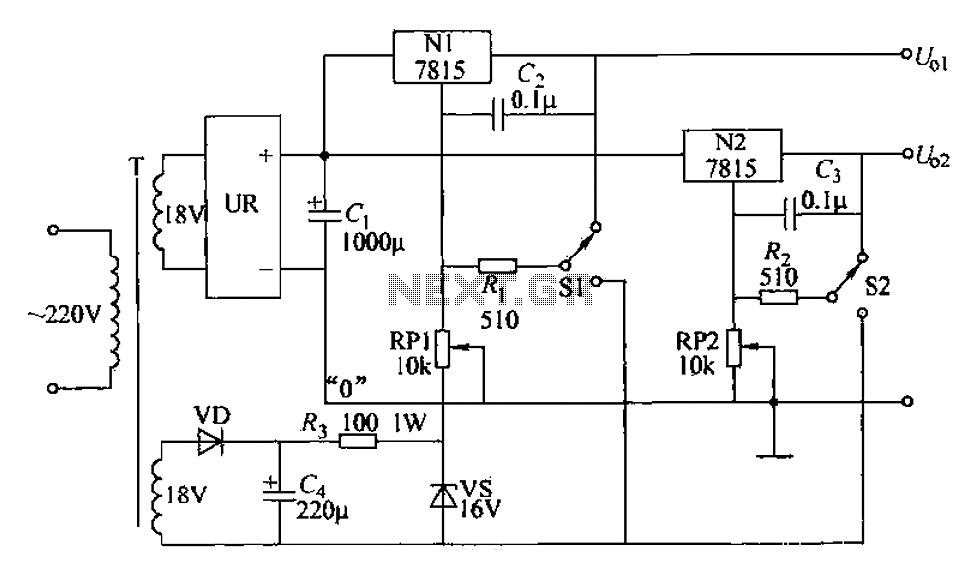
An adjustable dual voltage power supply circuit is presented, suitable for frequent experimental use. The current output does not exceed 1A, and both voltage outputs are adjustable. The circuit utilizes N1, N2, and 78 series three-terminal voltage regulator integrated...
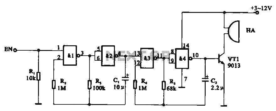
Tone generator circuit. The tone generator circuit utilizes a quad 2-input NAND gate integrated circuit, specifically the CD4011. NAND gates 1 and 2, along with NAND gates 3 and 4, form two gating multivibrator oscillators. The oscillation period of...
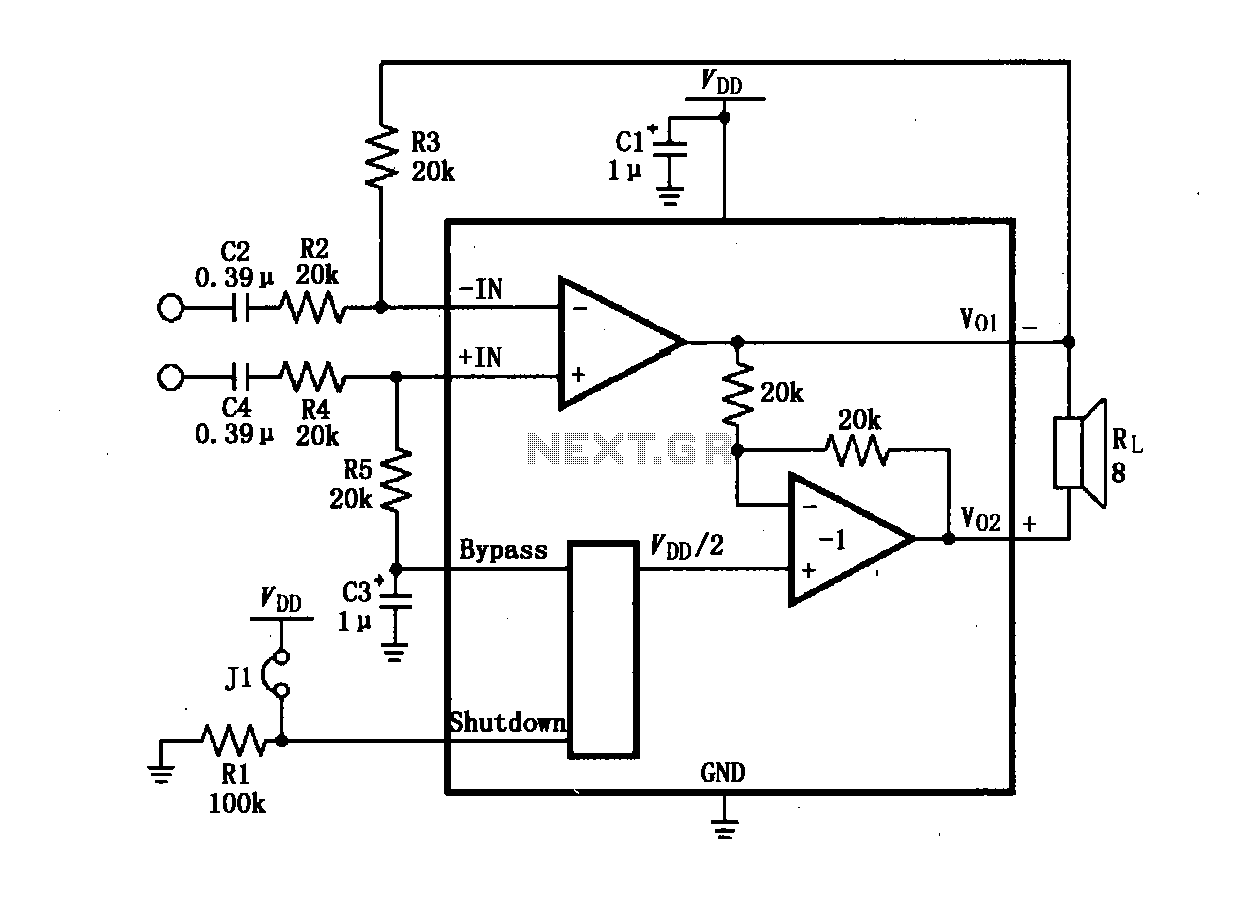
The LM4904 audio input differential amplifier circuit is presented. The audio signal is provided as a differential input to the +IN and -IN terminals. The LM4904 is a low-power audio input differential amplifier designed for high-performance audio applications. This circuit...
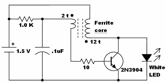
Here is an idea for a voltage booster that enables the lighting of a white LED using a single AA cell. This presents an opportunity to utilize one of the ferrite cores and white LED holiday lights mentioned in...