
Simple Light Seeking Robot
The robot's design integrates basic robotics principles suitable for educational purposes, allowing students to engage in hands-on learning experiences. The use of light-dependent resistors as sensors introduces fundamental concepts of light detection and response mechanisms in robotics. The incorporation of variable resistors for sensitivity adjustment enables students to experiment with different configurations, thereby enhancing their understanding of circuit dynamics.
The stripboard construction method serves as an excellent introduction to PCB design and soldering techniques. Students learn to navigate the layout of components, ensuring proper connections while adhering to safety protocols during soldering. The detailed instructions regarding the soldering process, including the handling of excess wire and the importance of joint cooling, provide practical skills that are essential in electronics assembly.
In terms of mechanical design, the aluminum chassis offers a lightweight yet sturdy platform for the robot, facilitating mobility and stability. The strategic placement of motors and the use of tie wraps for securing components illustrate effective methods for managing space and ensuring structural integrity. Furthermore, the attention to motor polarity emphasizes the importance of correct wiring in achieving desired movement outcomes.
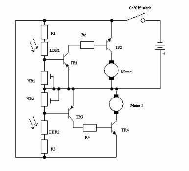
Overall, this project not only fosters technical skills but also encourages problem-solving and critical thinking, as students must troubleshoot issues related to sensor response and motor control. This comprehensive approach to robotics education equips students with foundational knowledge applicable to more advanced topics in electronics and engineering.This robot was designed as a project for secondary school pupils to build on an activity day. The chassis was provided to the pupils pre cut. The entire cost of the components per robot was just under GBP5 including the batteries. The robot is built on a small aluminium chassis and has two motors to move the robot left or right and two light depen dent resistors used as light sensors. If the robot senses light with the left sensor it will drive the right motor to turn the robot left and visa versa. If both light sensors receive equal amounts of light both motors will be driven to move the robot forward.
The two variable resistors are used to adjust the sensitivity of each channel. The transistors are used to amplify the small current flowing through the light dependent resistor to enable the current to drive the motor. The circuit diagram is shown in figure1. The main circuitry for the robot will be on stripboard. Stripboard consists of an insulating board with a square grid of holes drilled in it. Strips of copper link each row of holes, components such as resistors and transistors can be mounted on the plain side of the board with connecting wires passing through the holes.
These wires are then soldered to the copper strip. To solder onto the stripboard pass the wire ends of the components or connecting wire through the correct hole, you can bend the ends of the lead over slightly so that component does not fall out when you turn the board over. Hold the soldering iron so that the bit is against the copper strip of the stripboard and the wire of the component.
Touch both with the resin cored solder just long enough for the solder to flow freely. Be careful not to over heat the components or board, then remove the soldering iron and wait for the joint to cool. Now cut off the surplus wire as close to the board as possible. Be careful to hold the end of wire to stop it flying into the air. The robot is built on a small piece of 0. 1 ½ matrix stripboard 13 strips by 17 holes. Some of the strips need to have breaks in them as shown in figure 2. These breaks are made using a twist drill, these breaks are already made for you, the switch is also soldered onto the board.
The first items to be soldered to the stripboard are the wire links. The wire links are soldered onto the board first, followed by the resistors, variable resistors and transistors. Once the circuit is complete you will need to solder connecting wires to it, the position for these wires is shown in figure 3.
The circuit board can now be mounted on the chassis using the supplied nuts and bolts as shown in figure 4. The battery holder can now be bolted to the chassis, a short length of stiff wire is trapped under the front of the battery box to support the light dependent resistors.
The motors can the be fixed to chassis with tie wraps and all the interconnecting wires can be soldered to the relevant locations. The general layout and motor and battery wiring are shown in figure 5. Pay special attention to the polarity of the motors, if they are connected incorrectly the robot will go round in circle or may even go backwards.
To increase the traction of the robot, tyres need to be fitted these consist of piece of PVC sleeving over the motor shaft followed by a piece of rubber tubing as shown in cross section in figure 6. 🔗 External reference
Related Circuits
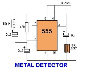
Assemble the circuit on a perfboard or PCB, excluding the inductor. Attach two long wires in place of the inductor. Use a long rod and position the inductor. The circuit assembly begins with the preparation of a perfboard or printed circuit...

A "Cell Jammer" is simply another term for a "Dirty Transmitter," which transmits within the cellular phone frequency bands. In reality, the more interference it generates, the more effective it is. A cell jammer operates by emitting signals that interfere...
Incorporate resistors in a parallel configuration to enhance audio input. To control the volume for each input channel, integrate a linear trimmer or potentiometer with the following configuration: pin 1 connects to ground, pin 2 serves as the output,...
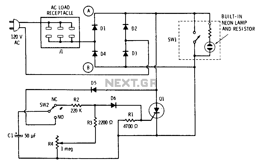
The push button and potentiometer initiate a time delay that turns a light on and then automatically turns it off again after a predetermined time. The potentiometer can be set for a delay of a few seconds to just...
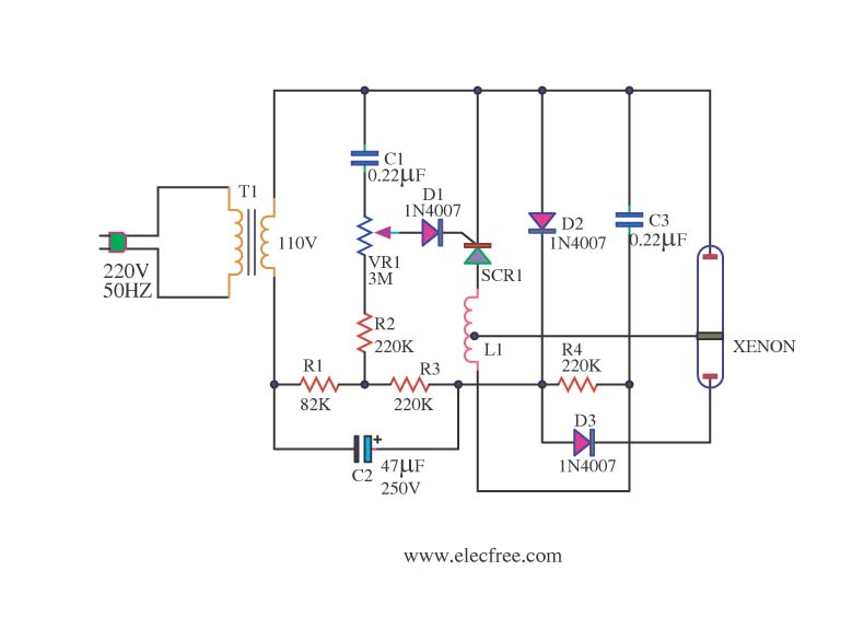
This is a Xenon Strobe Light circuit that utilizes a Xenon tube to produce various brightness levels. The blinking speed can be finely adjusted to be fast or slow using VR1. The circuit incorporates a Silicon Controlled Rectifier (SCR). The...
This line-following robot sensor, also known as a surface scanner for robots, is a compact, stamp-sized infrared proximity detector designed for short-range detection, typically within 5 to 10 mm. The line-following robot sensor operates using infrared light to detect the...