
simple metal detector

The circuit assembly begins with the preparation of a perfboard or printed circuit board (PCB) as the base for mounting the components. The inductor, which is a critical component in many electronic circuits, is intentionally excluded from the initial assembly. Instead, two long wires are attached at the designated location where the inductor would typically be connected. This approach allows for flexibility in testing and tuning the circuit without the inductor's influence during the initial setup.
Next, a long rod is used to position the inductor. This rod serves as a means to create a variable inductance effect, enabling adjustments to be made based on the circuit's performance during testing. The use of a rod allows for easy manipulation of the inductor's placement, which can significantly affect the circuit's overall behavior, particularly in applications involving RF (radio frequency) or tuned circuits.
It is essential to ensure that all connections are secure and that the wires are appropriately insulated to prevent any unintended short circuits. The circuit should be powered on only after verifying that all components are correctly placed and connected. Testing can then commence to evaluate the circuit's performance, with adjustments made as necessary based on the results observed. This method provides a practical approach to circuit assembly, allowing for modifications and enhancements in real-time.Assemble the circuit on a perfboard or pcb except the inductor. Attach two long wires at the place of the inductor. Use a long rod and place the induc.. 🔗 External reference
Related Circuits
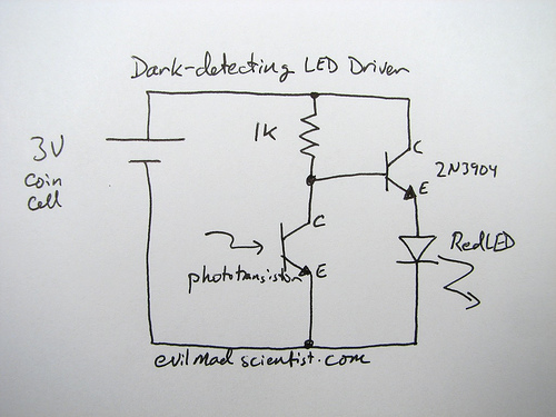
The following circuit illustrates a simple and inexpensive dark-detecting LED circuit. Features include the use of photoresistors, specifically a photocell or LDR, and an LED. This circuit utilizes a light-dependent resistor (LDR) as the primary sensing element. The LDR exhibits...

The comparator output drives an LED, and the next step is to sense the intensity of the LED. This lab involves building a light detector circuit using an operational amplifier (op-amp) and a standard light-emitting diode (LED). It is...
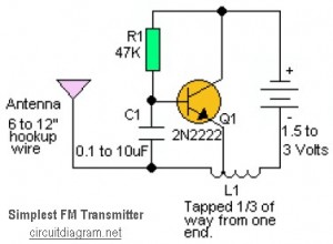
This is likely the simplest radio transmitter available. It comprises five components and can be assembled in a compact space. It is ideal for science fair projects or other science-related activities where short-range transmission is beneficial. The device operates...

The piezoelectric element of a kitchen gas lighter is utilized in this simple yet effective seismic detector. The piezo element must be positioned vertically, with one end firmly grounded. A loose package containing 2-3 pounds of fine gravel should...

This circuit is the simplest inductive balancing metal detector (IB, Induction Balance) that can be constructed. The LB metal detection method offers satisfactory depth of penetration and effectively distinguishes between iron-based and noble metallic objects. While several metal detectors...

The circuit features an integrated analog multiplier, the MC1596, functioning as a synchronous detector. It is designed to demodulate amplitude-modulated signals sourced from an integrated circuit. The output signal is derived from the O pin, where a local carrier...