
Xenon Strobe Light 110V by SCR

The Xenon Strobe Light circuit is designed to generate high-intensity flashes of light, making it suitable for applications such as photography, visual effects, and signaling. The core component, the Xenon tube, operates by ionizing gas within the tube, allowing it to produce a bright flash when a high voltage is applied.
The circuit's operation begins with the charging of a capacitor, which stores energy until it reaches a predetermined voltage. At this point, the SCR is triggered, allowing the stored energy to discharge rapidly through the Xenon tube, resulting in a bright flash. The brightness of the flash can be adjusted by varying the charge voltage, which is controlled through a variable resistor (VR1). This feature enables the user to select the desired intensity of the light output.
In addition to brightness control, the blinking speed can be modified by adjusting the timing components in the circuit. This typically involves changing the values of resistors and capacitors associated with the SCR trigger circuit, allowing for a wide range of flashing rates from rapid strobe effects to slower, more pronounced flashes.
The circuit may also include additional components such as diodes for protection against back EMF, which can potentially damage the SCR or other sensitive components. A power supply is necessary to provide the required voltage for the Xenon tube, which is typically in the range of 300 to 400 volts, depending on the specific tube used.
Overall, the Xenon Strobe Light circuit is a versatile and effective solution for generating high-intensity flashes of light, with adjustable brightness and blinking speed, suitable for various applications in both professional and hobbyist settings.This is Xenon Strobe Light circuit, model continual use a tube Xenon at give many brightnesses. By can fine blink fast or slow get , with VR1. By have SCR. 🔗 External reference
Related Circuits
This project involves a light-activated alarm or morning alarm circuit that produces a pleasant melody upon detecting light. To use this circuit as a morning alarm, it should be placed in a location that receives morning sunlight. A 500K...

The zener diode maintains a constant voltage of 20 V for the unijunction transistor Q1, except at the end of each half-cycle of the input when the line voltage drops to zero. Initially, the voltage across capacitor C1 is...

1999 Civic Wiring Diagram for Courtesy Lights Manual PDF. The 1999 Civic Wiring Diagram for courtesy lights provides a comprehensive visual representation of the electrical connections and components associated with the vehicle's interior lighting system. This schematic is essential for...
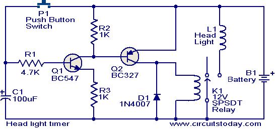
This circuit is a compact timer that keeps the headlights of a car on for approximately 1.5 minutes before turning them off. Incorporating this circuit into a vehicle allows access to dark areas without the need to return and...
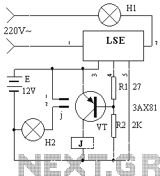
The device circuit operates as illustrated in Figure 11. Power outages are a common occurrence, but in certain situations, maintaining power is critical, such as during ongoing surgeries. The circuit employs a simple design that is fully automated. When...

This light sensor switch circuit enables the automatic activation of a lamp when ambient light levels decrease, such as during nightfall. The duration for which the lamp remains on can be adjusted using potentiometer P1, with a range of...