
Watchdog Timer/Alarm
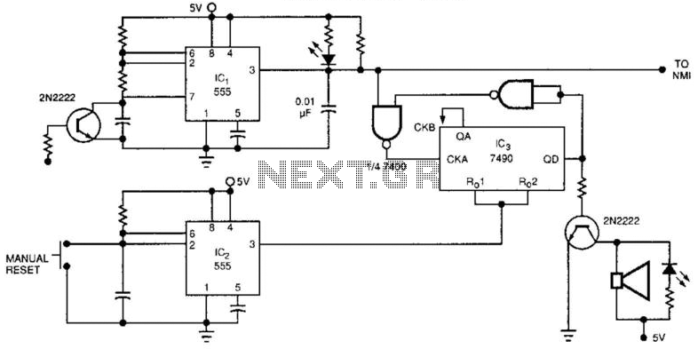
The described watchdog timer circuit is a critical component for monitoring the operational state of electronic systems. It employs a retriggerable 555 timer (IC1) to monitor system performance and a counter (IC3) to track the number of reset attempts. If the system fails to restart after eight attempts, the counter triggers an audible alarm, alerting users to a system failure.
IC1 operates in a monostable mode, where it generates a pulse each time it is triggered. This pulse is used to reset the counter, IC3. The counter is configured to count the number of reset attempts. Once the count reaches eight, it indicates a persistent failure, prompting the system to activate an alarm signal. This alarm can be implemented using a simple piezo buzzer or speaker, providing an audible notification of the issue.
The second 555 timer (IC2) plays a vital role in managing the reset process. It is configured to reset the counter (IC3) during manual restart procedures, ensuring that users have the opportunity to attempt a reset without triggering the alarm prematurely. The design can be further enhanced by integrating an automatic reset feature, allowing the system itself to reset the counter after a successful restart. This modification could improve the reliability of the circuit by minimizing unnecessary alarm activations.
In summary, this watchdog timer circuit is designed to enhance system reliability by monitoring operational status and providing alerts in case of failures. Its use of a retriggerable 555 timer and a counter allows for effective tracking of reset attempts, while the incorporation of an alarm system ensures that users are promptly informed of any critical failures. The watchdog timer contains a counter, IC3, in addition to the usual retriggerable 555 timer, ICl. The counter will so und an audible alarm if the watchdog timer trys to reset the a certain number of times (8, in the case of the counter). The alarm indicates that despite numerous resets, the system has failed to restart successfully, and the system is truly dead.
A second 555 timer, IC2, resets the counter, 1C3, for the duration of the manual system restart. The design could be modified so that system resets the counter. 🔗 External reference
Related Circuits
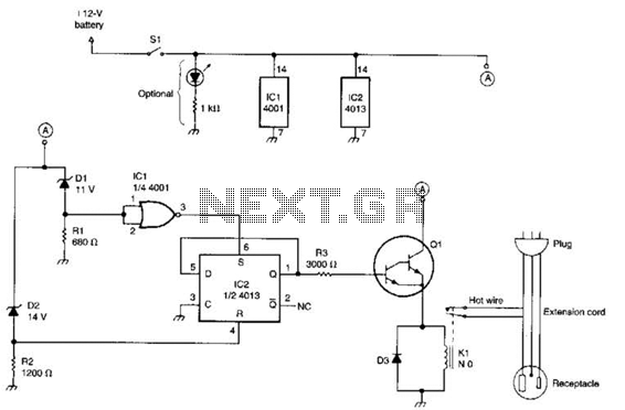
This circuit utilizes a pair of Zener diodes to monitor the voltage of a 12-V battery. When the voltage drops below 11 V, diode D1 ceases to conduct, causing pin 3 of flip-flop IC2 to go high. This action...
This article is the result of positive feedback on previous hardware articles. Readers of LinuxFocus expressed interest in interfacing with the USB bus. This solution utilizes the LCD display from a May 2002 article and connects it to the...

The electronic watchdog circuit functions similarly to a traditional guard dog, monitoring a 10-meter area around a door. When someone enters this monitored zone, the circuit emits a realistic barking sound. This sound can be sustained for 10 seconds,...
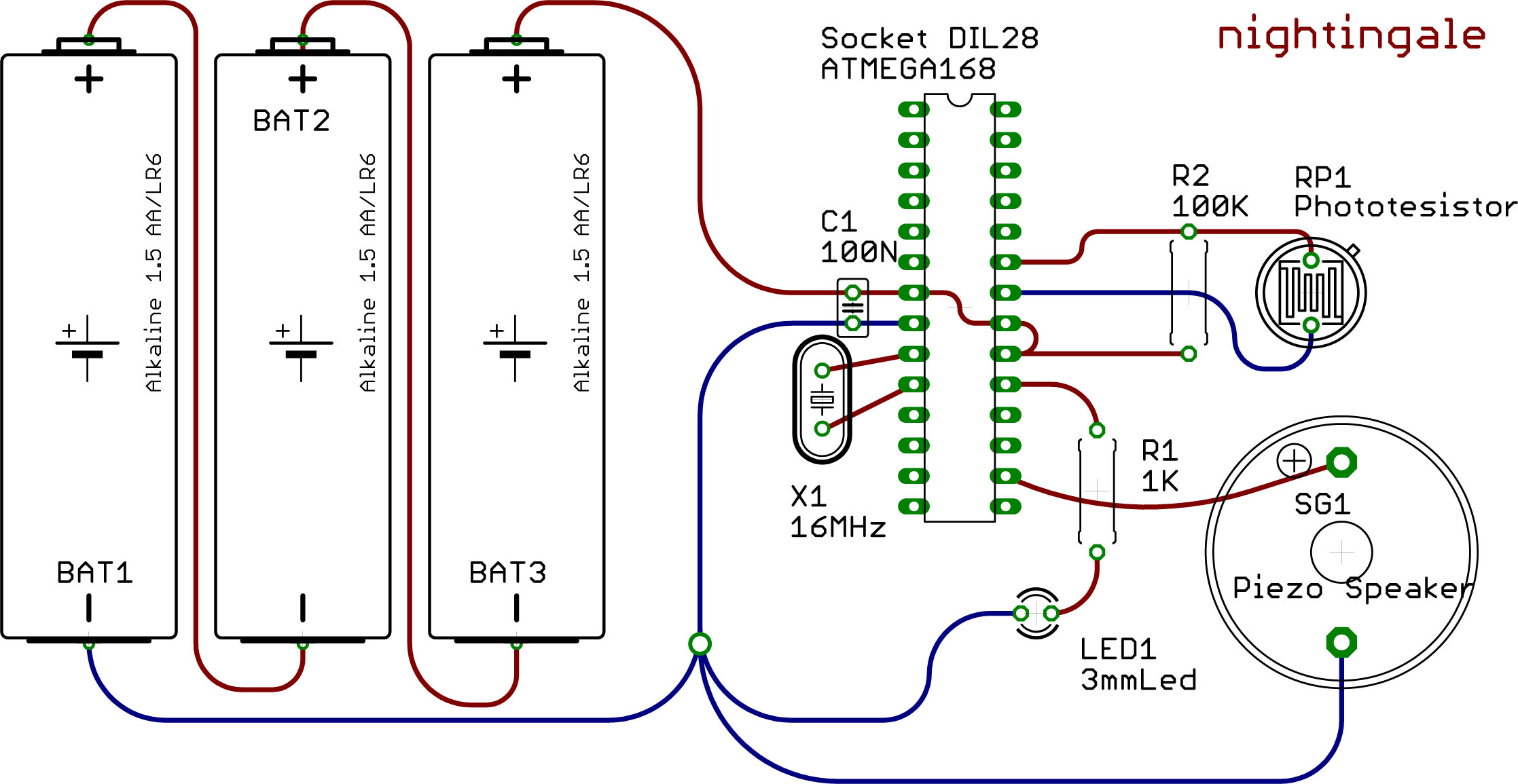
This example demonstrates the utilization of the Watchdog and Sleep functions provided by the ATMEGA 168 microcontroller. These functions are beneficial for developing low-power devices powered by batteries or solar energy. Reduced power consumption is achieved through intermittent operation...
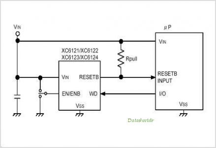
The XC61H series is a highly accurate, low power consumption CMOS voltage detector featuring a delay circuit. The detection voltage maintains high accuracy with minimal temperature drift. Output configurations are available in both CMOS and N-channel open drain. As...
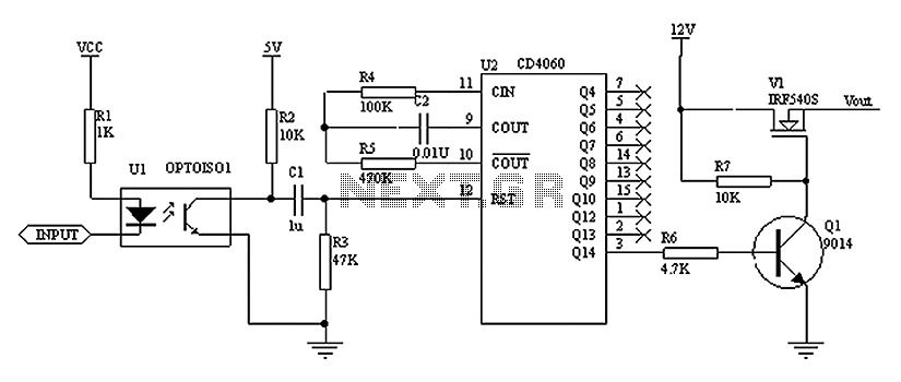
As shown in the figure, the operation of the circuit relies on the timing of the reset pulse to the CD4060. This ensures that the state is finalized in Q1, allowing the NMOS transistor to control the LED, keeping...