
Simple LM317 variable voltage supply does it limit current too
In this circuit, a variable voltage supply is designed to provide a controlled output of 5V, adjustable via a potentiometer. The 240-ohm resistor serves as a current-limiting component, ensuring that the current flowing through the load does not exceed a predetermined value, thereby protecting sensitive devices such as LEDs or solenoids from damage due to excessive current.
To determine the appropriate power rating for the resistor, the maximum current limit must be calculated based on the desired output voltage and the resistance value. The power rating can be calculated using the formula P = I²R, where P is the power in watts, I is the current in amperes, and R is the resistance in ohms. If the expected maximum current is 500mA, the power dissipated by the resistor would be P = (0.5)² * 240 = 60 watts. Therefore, a resistor with a power rating significantly higher than this value should be selected to ensure reliability and prevent overheating.
In addition to the resistor, a current-limiting circuit may be implemented after the voltage regulator to provide further protection. This could involve the use of a transistor or an integrated circuit designed for current regulation, allowing for precise control over the maximum current supplied to the load.
The circuit should also incorporate safety features such as fuses or thermal protection to prevent damage in case of component failure or short circuits. By ensuring that the circuit design includes these considerations, the risk of damaging sensitive components while testing various loads can be minimized, allowing for a safe and effective testing environment.Assuming I can get 5V in example after adjusting the pot in real use, will the 240 ohm resistor limit the current, or do I have to add something else on top of that afterwards If it does (I can have var. voltage + current limit) I assume I will need to up the resistor power specifications as the current will flow through them (or my after-regulator limiter) Specifically, I do not want a constant current source, because testing
a home-made solenoid or a random LED I assume the upper current limit I set will let them work and not be destroyed. I want this because I wish to set a limit rather than force 500mA to go through something it does not want to by raising the voltage well above 5V for example.
🔗 External reference
Related Circuits
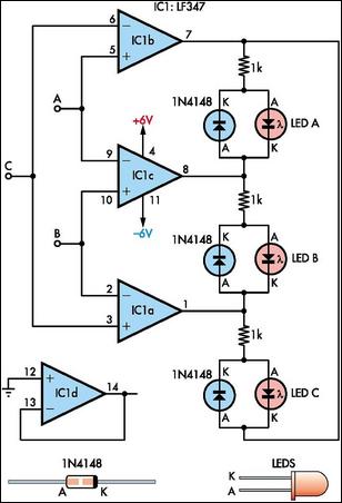
This circuit indicates which of three voltages, ranging from approximately -4V to +4V at points A, B, and C, is the highest by illuminating one of three indicator LEDs. Alternatively, it can be configured to indicate the lowest of...
The circuit diagram presented is for a compact mini audio power amplifier that operates with a DC supply voltage ranging from 4.5 volts to a maximum of 18 volts. This amplifier utilizes the TDA1015 integrated circuit, produced by NXP...
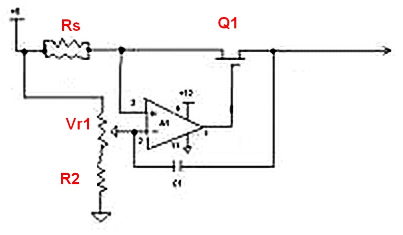
Features: 3-12 V, 1 A, over-current protection. This is a simple yet reliable device based on one of the oldest integrated voltage regulators, the LM723. R2 sets the output voltage. The maximum current is determined by the value of...
Normally, an analog-to-digital converter (ADC) requires interfacing through a chip to convert analog signals into digital format. This necessitates both hardware and software, resulting in increased complexity and overall cost. The circuit presented here is configured around the ADC...
Two reasons why the LM101 is well-suited for comparator applications are its large differential input voltage range and the ease of clamping the output. The LM101 operational amplifier is particularly advantageous for use in comparator circuits due to its significant...
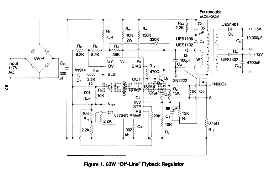
This paper gives a practical example of the design of an off-line switching power supply. Factors governing the choice of a discontinuous flyback topology are discussed. The design uses a pulsed-width modulation (PWM) control scheme implemented with a Unitrode...