
Simple Analog to Digital Converter (ADC)
")
The ADC 0808 is a versatile device widely used in applications requiring the conversion of analog signals to digital data. Its operation relies on the successive approximation technique, which allows for efficient conversion with minimal hardware requirements. This circuit configuration is particularly advantageous because it eliminates the complexity and cost associated with microprocessor interfacing.
In this design, the eight input channels enable multiple analog signals to be monitored and converted simultaneously. The use of address lines A, B, and C for channel selection streamlines the process, allowing the user to easily switch between different input sources. The active-high control signals ALE and OE ensure that the ADC is properly enabled and ready to convert the selected input signal.
The clock signal generated by the astable multivibrator is crucial for the timing of the conversion process. The frequency of approximately 550 kHz is optimal for the ADC 0808, ensuring that it operates within its specified performance parameters. The astable multivibrator can be constructed using standard 7404 inverter gates, which are readily available and inexpensive.
The output visualization using LEDs provides a straightforward method for monitoring the digital output in real-time. Each LED corresponds to a specific bit in the output data, allowing for immediate visual feedback of the conversion result. This feature enhances the usability of the circuit, making it suitable for educational purposes and practical applications alike.
In summary, the ADC 0808 circuit described here offers a cost-effective and efficient solution for analog-to-digital conversion, with a straightforward interface and real-time output visualization. Its design facilitates ease of use and flexibility, making it an excellent choice for various electronic applications.Normally analogue-to-digital con-verter (ADC) needs interfacing through a chip to catechumen alternation abstracts into agenda format. This requires accouterments and all-important software, consistent in added complication and appropriately the absolute cost.
The ambit of A-to-D advocate apparent actuality is configured about ADC 0808, alienated the use of a microprocessor. The ADC 0808 is an 8-bit A-to-D converter, accepting abstracts curve D0-D7. It works on the assumption of alternating approximation. It has a absolute of eight alternation ascribe channels, out of which any one can be called application abode curve A, B and C. Here, in this case, ascribe approach IN0 is called by accomplishments A, B and C abode lines. Usually the ascendancy signals EOC (end of conversion), SC (start conversion), ALE (address latch enable) and OE (output enable) are interfaced by agency of a microprocessor.
However, the ambit apparent actuality is congenital to accomplish in its affiliated approach afterwards application any microprocessor. Therefore the ascribe ascendancy signals ALE and OE, actuality active-high, are angry to Vcc (+5 volts).
The ascribe ascendancy arresting SC, actuality active-low, initiates alpha of about-face at falling bend of the pulse, admitting the achievement arresting EOC becomes aerial afterwards achievement of digitisation. This EOC achievement is accompanying to SC input, area falling bend of EOC achievement acts as SC ascribe to absolute the ADC to alpha the conversion.
As the about-face starts, EOC arresting goes high. At abutting alarm beating EOC achievement afresh goes low, and appropriately SC is enabled to alpha the abutting conversion. Thus, it provides affiliated 8-bit agenda achievement agnate to direct amount of alternation input. The best akin of alternation ascribe voltage should be appropriately scaled bottomward beneath absolute advertence (+5V) level.
The ADC 0808 IC requires alarm arresting of about 550 kHz, which can be calmly acquired from an astable multivibrator complete application 7404 inverter gates. In adjustment to visualise the agenda output, the row of eight LEDs (LED1 through LED8) accept been used, wherein anniversary LED is affiliated to corresponding abstracts curve D0 through D7.
Since ADC works in the affiliated mode, it displays agenda achievement as anon as alternation ascribe is applied. The decimal agnate agenda achievement amount D for a accustomed alternation ascribe voltage Vin can be affected from the relationship
🔗 External reference
Related Circuits
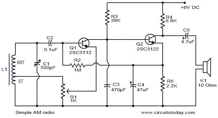
This is a straightforward AM radio circuit utilizing only two transistors. The coil L1 and variable capacitor C1 create the tank circuit. Transistor Q1 is responsible for demodulation, and the demodulated signal is accessible at the base of Q1....
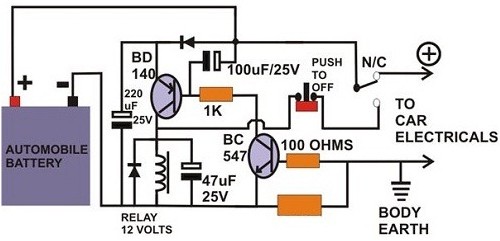
A circuit breaker is an electronic device that functions to protect an electrical circuit from hazards or damage caused by overloads or short circuits. A circuit breaker operates by automatically interrupting the flow of electricity when it detects an...
Even if simple the circuit, plirej' all condition, regarding the distortion and the response of frequency. The resistance of entry is 250K and the load that can drive is between 100R and 2K. The circuit use negative coupling. His...
This circuit utilizes the widely available and user-friendly LM3914 integrated circuit (IC). The LM3914 is straightforward to operate, does not require external voltage regulators due to its built-in voltage regulation, and can be powered by nearly any voltage source....
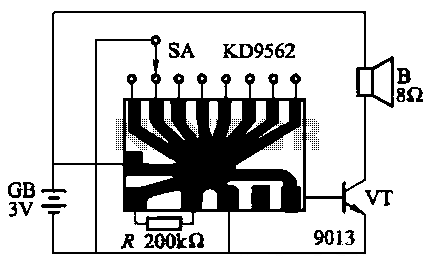
The KD9562 music octave circuit is an analog sound circuit capable of producing various sound effects including rifle shots, space shots, game console sounds, dual-tone doorbells, bomb explosions, machine gunfire, and ambulance sirens. The main electrical parameters are as...
This involves controlling servo motors through software programming using the PIC 16C71 microcontroller. The input signals range from 0 to 5V. The circuit utilizes the PIC 16C71 microcontroller, which is an 8-bit device suitable for controlling servo motors. The microcontroller...