
Simple logarithmic amplifier circuit

The logarithmic amplifier circuit designed around the LT1012 operational amplifier is a crucial component in applications requiring the conversion of a wide range of input voltages into a logarithmic scale. The LT1012 is characterized by its low bias current, which is essential for achieving high accuracy in logarithmic amplification, particularly over a range of 4.5 decades. This feature minimizes the offset errors that can arise from input bias currents, ensuring that the output closely follows the logarithmic relationship of the input voltage.
In this circuit, the LT1012 is configured in a feedback arrangement that allows the input voltage to be logarithmically processed. The transistors, such as the 2N2979, can be incorporated to enhance the performance of the logarithmic amplifier. The 2N2979 is a high-speed transistor that can be utilized in the feedback loop or as part of the input stage to improve the linearity and response time of the circuit.
The overall design should include careful consideration of the resistor values in the feedback network, as these will dictate the gain and the logarithmic scaling factor. Capacitors may also be included to stabilize the amplifier and filter out any noise that could affect the accuracy of the logarithmic output.
The output of the circuit can be used in various applications, including signal processing, audio level measurement, and any system where a logarithmic representation of the input signal is beneficial. Proper layout and component selection are critical to ensure minimal distortion and optimal performance of the logarithmic amplifier circuit.This simple logarithmic amplifier circuit use the LT1012 which has a low bias current allow 4 1/2 decades off voltage input logging. Transistors that can be used here could be the 2N2979..
Related Circuits
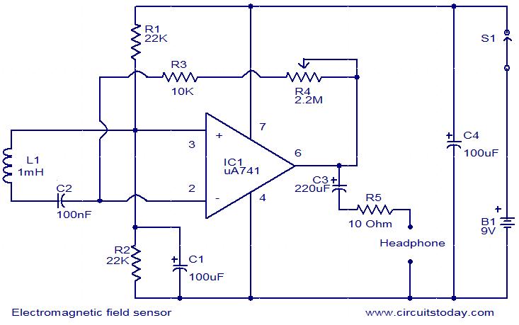
This is a very simple circuit that can be used to sense electromagnetic radiations. The circuit can even detect hidden wires. A 1mH inductor is used for sensing the electric field. The electric field will induce a small voltage...
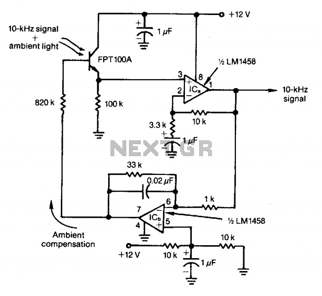
The feedback control of the phototransistor in this optical detector helps negate the effects of varying ambient light sources. The output of a modulated visible-light LED is detected, amplified, buffered, and fed through a low-pass filter. Ambient light signals...
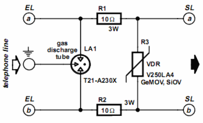
A long time ago, when telephones were simple and reliable from an electrical standpoint, telecom operators installed surge protection on all telephone lines at risk from storms. Paradoxically, as modern technology has led to the use of delicate and...
This is a less polished version of Handmade Electronic Music, featuring nearly identical content and available for free. Notably, refer to Chapters 18 and 20. The layout consists of conductive metal strips beneath the perforations of the breadboard. Typically,...
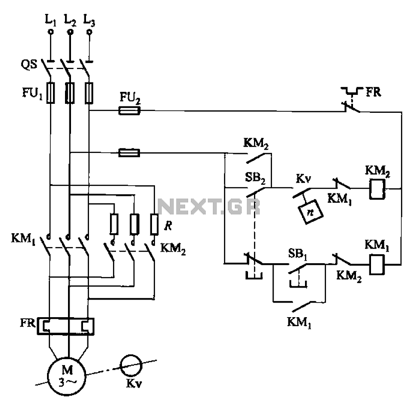
The circuit depicted in Figure 3-124 operates without an intermediate relay. Kv serves as the speed relay, activating when the electric motor speed exceeds 120 r/min while the contact is closed. If the speed drops below 100 r/min, the...
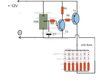
The circuit is an LED driver that responds to ambient light as well as the presence of an intruder, varying its illumination accordingly. Additionally, it includes an ambient light sensor to turn the LEDs on and off, and a...