
Modulated light-beam circuit
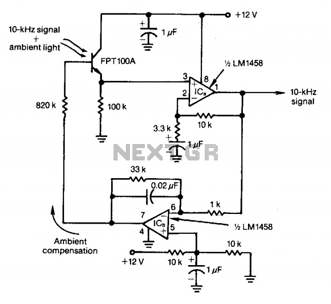
The optical detector circuit employs a phototransistor that serves as the primary sensing element. The phototransistor is configured to receive light from a modulated LED, which operates at a frequency of 10 kHz. This modulation allows for the differentiation between the desired signal and ambient light interference, which typically contains a broad spectrum of frequencies.
The output from the phototransistor is first amplified using a transistor amplifier stage. This amplification is crucial for improving the signal-to-noise ratio, ensuring that even weak signals can be accurately processed. Following amplification, the signal is buffered to prevent loading effects that could distort the signal integrity. The buffer stage isolates the phototransistor from subsequent processing stages, maintaining the fidelity of the detected signal.
To further refine the output, the signal is passed through a low-pass filter. This filter is designed to attenuate frequencies above the modulation frequency of the LED, effectively removing any high-frequency noise, including signals from ambient light sources that do not correlate with the 10 kHz modulation. The result is a clean, stable output signal that accurately represents the intensity of the modulated LED light.
Additionally, the feedback control mechanism plays a critical role in enhancing the performance of the optical detector. By utilizing feedback from the output signal, the system can dynamically adjust the gain of the amplifier or alter the characteristics of the filtering stage to compensate for variations in ambient light. This feedback loop ensures that signals from ambient light sources, which are generally out of phase with the modulated LED signal, are effectively canceled out. The overall design allows for reliable operation in environments with fluctuating light conditions, making it suitable for various applications, including remote sensing and optical communication systems.Feedback control of the phototransistor in this optical detector helps negate the effects of varying ambient light sources. The output of a modulated visible-light LED is detected, amplified, buffered, and fed through a low-pass filter.
Ambient light signals below the LED's 10-kHz modulating rate reach the detector's base out of phase with incoming ambient light and cancel the undesired effects. 🔗 External reference
Related Circuits
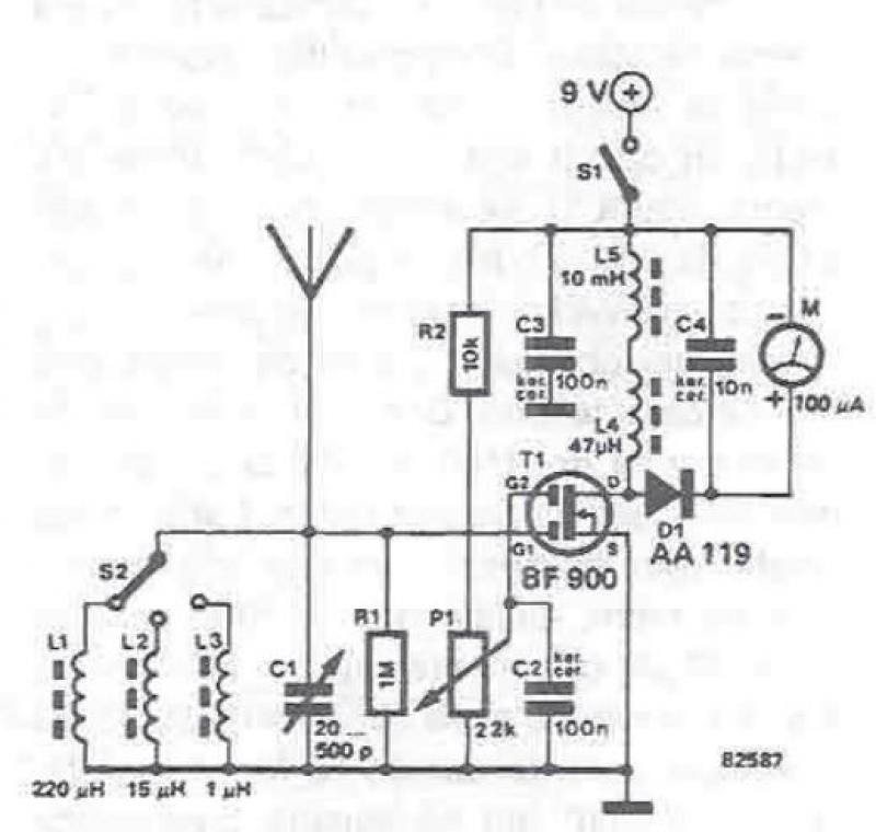
An RF field detector circuit suitable for measuring and verifying the power of antennas and transmitters can be constructed using transistors and common electronic components. This circuit employs a radio frequency transistor, specifically a MOS-FET with two gates. The...
The 74AC240 stepper driver works by alternately enabling each half of the buffer. Only one half can be enabled at a time. Let’s assume that the top half of the driver is enabled. U1A & U1B along with R8,...
The PowerSaver Flasher uses capacitive output coupling to produce brighter shorter flashes and has a much lower average current drain than standard bicore or 74HC14 flashers. The PS Flasher with one LED circuit (2 LEDs) runs all night from...

In this multivibrator circuit, frequency and pulse width can be separately controlled by using steering diodes (1N914) and two potentiometers. This multivibrator circuit utilizes steering diodes, specifically the 1N914 type, to enable independent control over both the frequency and pulse...
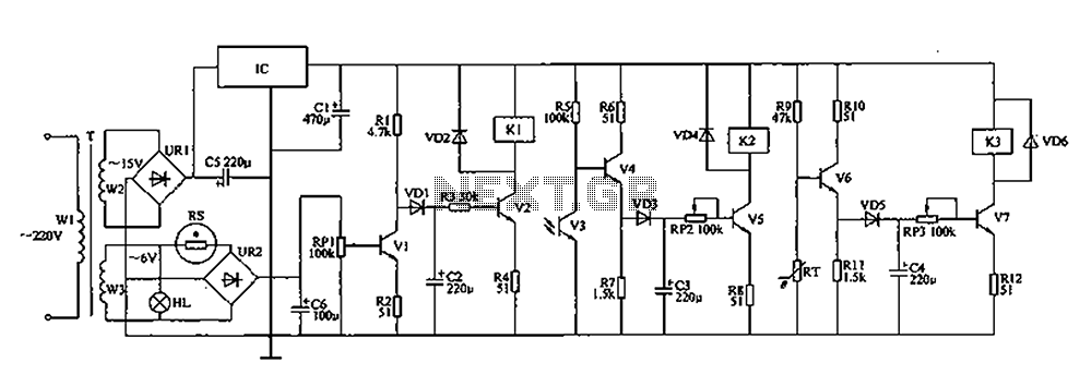
The automatic controller for a chicken coop is designed to automatically regulate light, temperature, and humidity, thereby enhancing egg production and survival rates of chickens. This device is intended for specialized poultry households in rural areas. The circuit operates...

This simple circuit will energize and de-energize a relay with the push of a button. Pressing the button once will energize the relay, while pressing it a second time will de-energize the relay. The accompanying circuit provides a solid...