
One-way operation of the brake circuit reverse

The circuit design incorporates a speed relay (Kv) that plays a crucial role in monitoring and controlling the operational speed of an electric motor. The functionality is contingent upon the motor speed, with specific thresholds set at 120 r/min and 100 r/min. When the motor operates above 120 r/min, the relay remains engaged, allowing the system to function normally. However, once the speed drops below 100 r/min, the Kv relay disengages, which triggers a series of actions to ensure safe operation.
Upon disengagement of the Kv relay, the KMi contact is released, which signifies that the motor should cease operation. Concurrently, KMz is activated to engage plug braking, a method that reverses the motor phase connections to rapidly decelerate the motor. This process is essential for applications requiring a quick stop to prevent damage or ensure safety.
The circuit includes a braking resistor (R) that serves to limit the reverse current generated during the braking phase. This is critical to protect the circuit components from potential damage due to excessive current. The resistor can be connected to only two of the three phases, providing flexibility in the circuit design while maintaining effective braking performance.
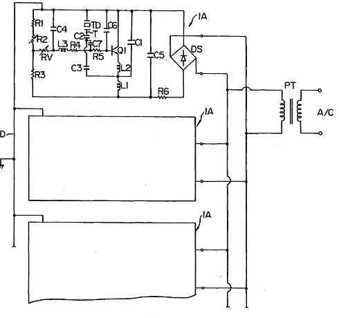
Once the motor speed has decreased to below 100 r/min, the Kv contacts open, which leads to the release of KM2. This action signifies the conclusion of the braking process, which is designed to last between 1 to 3 seconds, allowing for a controlled and safe stopping procedure. Overall, the circuit is designed to enhance the operational safety and efficiency of electric motor systems by integrating speed monitoring and responsive braking mechanisms. Circuit shown in Figure 3-124. The line does not use an intermediate relay. Figure, Kv is the speed relay, when the electric engine speed is greater than 120r/min when the cont act is closed, less than 100 r/min, the contacts open. Shutdown, contact KMi release put, KMz pull, plug braking. When the speed is lower than lOOr/min, Kv contacts open. KM2 release, the braking process ends (about 1 ~ 3s). Access braking resistor R purpose is to limit the reverse current brake. R can also be connected to only two phases.
Related Circuits
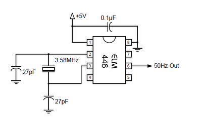
The ELM446 is an 8-pin digital divider integrated circuit that generates both 50Hz and 1Hz outputs from a common 3.58MHz NTSC colorburst crystal. The designer needs to supply only the crystal and two suitable loading capacitors, along with a...
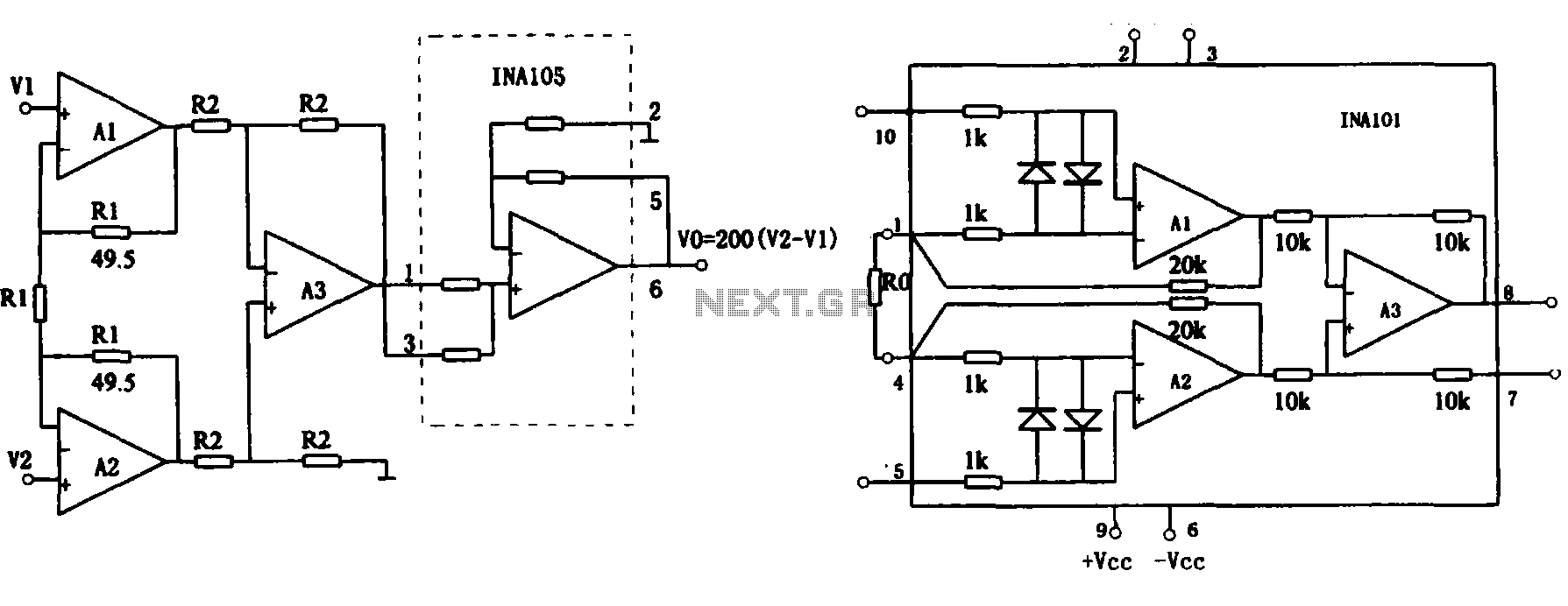
This document describes the extended common mode input voltage range of an instrument amplifier circuit. The circuit consists of three precision instrument amplifiers, A1, A2, and A3, which can be INA101 or INA102 models. The figure illustrates that A1,...
If you need a timer circuit, we go after the most proven 555. However, if the delays are longer, based on timing capacitor capacity is too large. In this case, a circuit of Figure 1 After pressing the button...
Ultrasonic atomizer circuit: How to generate an atomized water mist using ultrasonic sound waves. The ultrasonic atomizer circuit is designed to produce a fine mist of water by utilizing ultrasonic sound waves. This process involves the conversion of electrical energy...
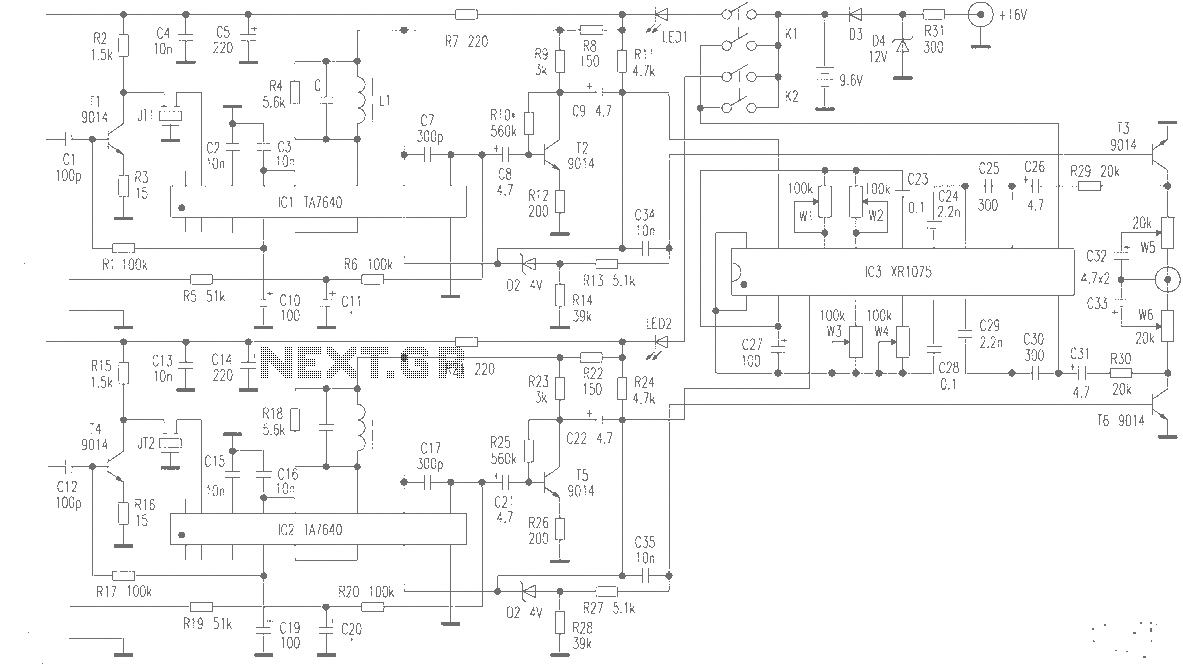
The production of high-quality wireless microphones is a common aspiration among enthusiasts, but achieving a high-performance receiver is challenging. This project explores the use of salvaged FM radio cassette players to enhance an XR1075 audio processor, leading to the...
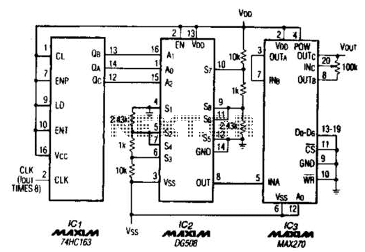
A TTL counter, an 8-channel analog multiplexer, and a fourth-order low-pass filter can generate sine waves ranging from 10 kHz to 25 kHz with a total harmonic distortion (THD) better than -80 dB. The circuit employs two cascaded second-order,...