
Light Detector

The light detector circuit described utilizes a light-emitting diode (LED) to sense ambient light levels through its photovoltaic effect. The circuit is designed around an operational amplifier configured as a transimpedance amplifier, which converts the small current produced by the LED when exposed to light into a measurable output voltage. The LED operates in reverse mode, generating a current when illuminated, which is then amplified by the op-amp.
In the schematic, the LED is connected in reverse bias to the op-amp input. The output voltage (V_out) is taken from the op-amp's output pin and is linked to an analog input channel for real-time monitoring via an oscilloscope. The circuit's performance is characterized by the relationship between the light intensity and the output voltage, allowing for an intuitive understanding of ambient light levels. The LED's sensitivity to light wavelengths shorter than its emission spectrum is critical, as this characteristic enhances the accuracy of light detection.
In practical applications, the circuit can be utilized in various settings, including automatic lighting systems, light-sensitive alarms, and even in remote control systems, where infrared light detection is crucial. The ability to modulate the output of the LED and observe the corresponding changes in the output voltage allows for straightforward experimentation and calibration of the system.
In summary, the described light detector circuit effectively demonstrates the dual functionality of LEDs, serving both as light sources and sensors. Its design leverages the principles of operational amplifiers and the photovoltaic effect, offering a versatile tool for various electronic applications.With the comparator output driving an LED, the next step will be to sense the intensity of the LED. This lab will build a light detector circuit using an op amp and an everyday light emitting diode (LED). It`s common knowledge that when a current flows through an LED it emits light, but you may not have known that they also work in reverse.
When a n LED is exposed to light, it will create a small current from cathode to anode due to the photovoltaic effect. Using this property of LEDs, we can use them not only to produce light, but to detect it as well. This small current then can be amplified into a large voltage through the use of a transimpedance amplifier.
However there are some limitations to this approach. First, LEDs best detect light at wavelengthsshorter thanthe light they normally emit. This circuit will first be performed using the same type of blue LED that is used in the PWM Generator lab. This circuit will output a voltage that is proportional to the intensity of ambient light. The higher intensity the incident light the LED is exposed to, the higher the output voltage of the ambient light sensor circuit will be.
The following schematic will be used to sense ambient light. Build the circuit in the schematic below. Connect V_out to one of the analog input channels so that it can be observed on the oscilloscope. This circuit can be described very simply. When light shines on a LED there is a corresponding current that flows backwards through the LED (direction shown by red arrow in Figure Z. 1). Also, by characteristics of ideal operational amplifiers, both input terminals equal 0 volts. The blue arrows represent the direction of current that will be used to solve for output voltage in terms of resistance.
This means that a very small current can correspond to a measurable output voltage. To test this circuit shine the light from the LED on the output of the comparator directly at the LED of the light detector (point the tops of the LEDs towards each other). By increasing the output of the DAC the LED will get brighter and the measured voltage on the output of the light detector circuit will increase.
By setting the output of the digital I/O pins to 0111 1111, or half of full value the following capture was made. Notice that the Frequency of the captured waveform is at 2. 694 kHz which is what the frequency of the triangle wave generator was set at. Also note that the duty cycle of the captured is at 49. 8% due to the fact the DAC was set at 50% of full scale. Most remote controls for electronic appliances use a near infrared diode to emit a beam of light that reaches the device.
A 940 nm wavelength LED is typical. This infrared light is invisible to the human eye, but picked up by sensors on the receiving device. By turning on and off the diode at a specific frequency and modulating (adding or mixing) data (keystrokes from the remote), a device can communicate wirelessly to the intended target (tv, radio, etc. ). Looking back at your experiment, you can imagine an infrared detector in the appliance that will convert the pulses of light received to digital data.
Different manufacturers of infrared remote controls use different protocols to transmit the infrared commands. The RC-5 protocol that has its origins within Philips, uses, for instance, a total of 14 bits for each button press.
The bit pattern is modulated onto a carrier frequency that, again, can be different for different manufacturers and standards, in the case of RC-5, a 36kHz carrier is being used. Other consumer infrared protocols are, for instance, the different SIRCS versions used by Sony, the RC-6 from Philips, the Ruwido R-Step, or the NEC TC101 protocol.
By changing the LED in the previous section from Blue to Yellow the IR light can be sensed in an everyday remote control. Below is a capture taken from pointing a remote control at the light detector circuit with and yellow LED in p
🔗 External reference
Related Circuits

The circuit is depicted in Figure 1, while the electrical schematic diagram is presented in Figure 2. The AC voltage of 220V is reduced by components C3 and R3. The diodes VD1 and VD2 rectify the voltage, and capacitors...
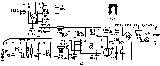
This circuit utilizes the KA2184 infrared receiver ASIC for an infrared remote control dimmer light application, as depicted in the schematic. The infrared signal is generated by a pulse generator using an NE555 timer integrated circuit. The NE555 produces...
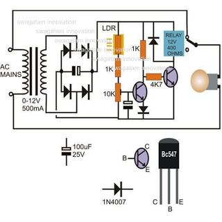
This circuit diagram illustrates a light-activated switch utilizing the National Semiconductor comparator IC LM311 and a light-dependent resistor (LDR). The configuration is based on a voltage comparator circuit centered around IC1. The non-inverting input of IC1 receives a reference...
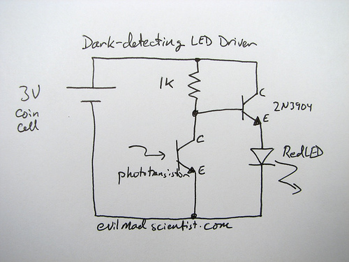
A circuit that uses a phototransistor to create a light-sensitive switch. When there is no light in the room, the LED connected to the phototransistor lights up, and when there is light, the LED turns off. Any schematic or...

This smoke detector employs a MEM 817 p-channel enhancement mode MOSFET as its buffer amplifier. The sensor operates on the principle that the current decreases when smoke enters the chamber, leading to a negative voltage change at the gate...

The circuit of automatic emergency light presented here has the following features: 1. When the mains supply (230V AC) is available, it charges a 12V battery up to 13.5V and then the battery is disconnected from the charging section....