
Simplest RF Transmitter

The radio transmitter circuit described is characterized by its simplicity and effectiveness, making it an excellent choice for educational purposes or experimental projects. The primary components include resistors (R1 and R2), capacitors (C1, C2, and C3), a transistor (Q1), and an inductor (L1). Each component plays a critical role in the circuit's overall functionality.
R1, typically valued at 4.7K ohms, serves as a biasing resistor for the transistor, influencing the base current and thus the overall gain of the circuit. R2, with a value of 330 ohms, is used to limit the current flowing through the circuit, protecting sensitive components from excessive current.
Capacitor C1, rated at 0.001 µF (1 nF), is crucial for determining the frequency of oscillation in conjunction with the inductor L1. Adjusting C1 allows for fine-tuning the transmission frequency, making the circuit versatile for various applications. Capacitor C2, with a value ranging from 10 to 40 pF, and C3 at 4.7 pF, further assist in frequency stabilization and modulation.
The 2N3904 transistor (Q1) is a commonly used NPN transistor that amplifies the audio signal from the electret microphone. The choice of transistor can significantly affect circuit performance, with variations in gain and frequency response.
The inductor L1, constructed from 20 to 30 turns of thin magnet wire, is essential for generating the radio frequency signal. The tapping point on the coil allows for feedback necessary for oscillation, with the tap connected to the emitter of the transistor.
The circuit can be powered by a low voltage source, making it suitable for portable applications. When combined with an electret microphone, the circuit effectively transmits audio signals over short distances, making it useful for various wireless communication projects.
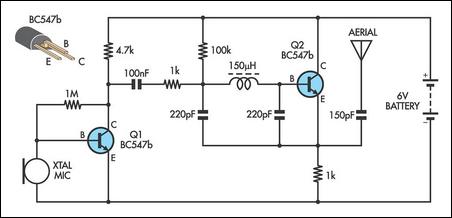
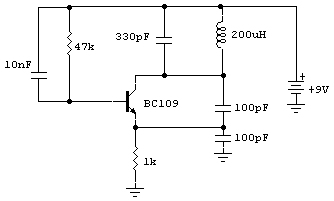
Overall, this radio transmitter circuit exemplifies a straightforward approach to RF transmission, allowing for experimentation and learning in electronics. The performance can be optimized through adjustments to component values, making it a flexible platform for further exploration in radio frequency technology.This is probably the simplest radio transmitter that you will find anywhere. It has a total of five parts and can be constructed into a very small space. It is great for science fair projects or other science related projects where short range transmission is useful. It runs on 1. 5 to 3 Volts, with small hearing aid batteries or lithium coin ce lls being ideal. A thermistor or photoresistor can be inserted in series with R1 to have a varying output frequency dependent on the input. The frequency can also be changed by changing the value of C1. A 2N2222 transistor is recommended, but you can try other types also. Performance tends to vary from type to type as well as from transistor to transistor. L1 is 20 to 30 turns of thin magnet wire (24 to 32 ga. ) close wound around a 1/8 to 1/4 ³ diameter non-conductive form. The coil is tapped 1/3 of the way from one end and the tap connected to the emitter of Q1. Experiment with all of the values in this circuit. Nothing is critical, but performance can be varied considerably. Tags: cheap RF Transmitter, easy RF Transmitter, RF Transmitter circuit, RF Transmitter design, RF Transmitter diagram, RF Transmitter schematic, simple RF Transmitter, The following diagram is the circuit diagram of Voice Transmitter which use FM signal carrier to transmit the vioce signal to the FM receiver device.
Components List: R1 = 4. 7K R2 = 330 ohm C1 = 0. 001uF (1nF) C2 = 10-40pF C3 = 4. 7pF Q1 = 2N3904 L1 = see text Misc = Electret mike, . This the Good Quality FM transmitter for your stereo or any other amplifier gives you a pretty good signal strength up to a range of 500 metres having a power output of about 200 mW. This circuit can be operated with a 9V battery. The audio-frequency modulation stage is constructed close to transistor BF494 (T1), . The following diagram is the FM tracking transmitter based on 4 transistors. No additional notes for this tracking transmitter diagram, try to discover this circuit by yourself. :) Components list: R1 = 100K Ohms R2 = 10 Ohms R3 = 47K Ohms R4 = 220 Ohms C1 = 4. 7uF/16V C2, C5 = 1nF C3 =. Easy FM tracking transmitter project :). The circuit designed by Tony van Roon, and here the FM tracking transmitter diagram: Components List: R1 = 10K C1 = 100uF/10V C2 = 10nF C3 = 4-40pF trimmer capacitor C4 = 4.
7pF IC1 = LM3909 Q1 = 2N3904 NPN transistor LED1 = Red LED/or another color as you. Above diagram is a very easy and efficient receiver for actuating garage doors, starter motors, alarms, warning systems and many some other possibilities. The SCR, which has a extremely low trigger current of 30 uA is typical - it demands an input electricity of just 30 uW to activate the relay.
A high Q tuned. 🔗 External reference
Related Circuits
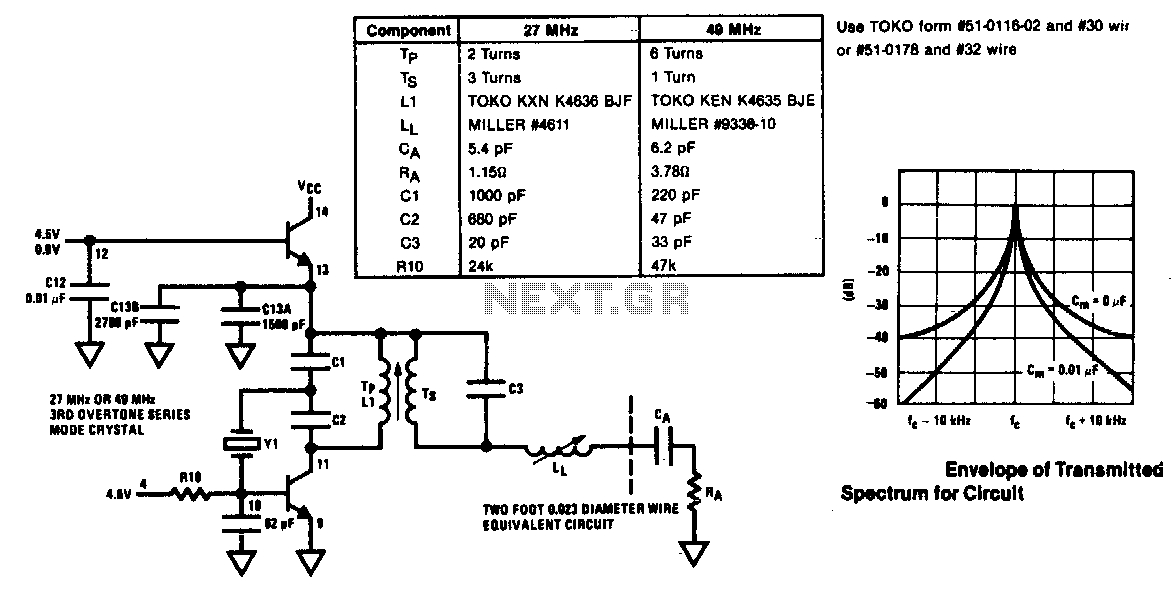
The modulator and oscillator comprise two NPN transistors. The base of the modulator transistor is powered by a bidirectional current source, with the voltage range for the high condition restricted by a saturating PNP collector connected to the pin...
This AM transmitter is designed for simplicity, featuring a non-tapped inductor with a single winding. The inductor is a standard RF choke, such as the Jaycar Cat LF-1536, eliminating the need for custom winding. To minimize the circuit's size,...
The AM transmitter circuit consists of an audio amplifier and an RF oscillator. The oscillator is constructed around transistor Q1 and its associated components. The tank circuit, which includes inductor L1 and variable capacitor VC1, is tunable from approximately...
Circuit of a crystal-controlled FM transmitter. The circuit utilizes a crystal oscillator and several power amplifier stages to enhance output power. The crystal-controlled FM transmitter circuit is designed to generate frequency-modulated signals with high stability and precision. At the core...
An inquiry was received regarding an oscillator used in an AM transmitter. Research was conducted online, leading to the discovery of a relevant circuit. According to the author... The oscillator circuit for an AM transmitter typically serves as the primary...
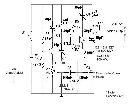
Tuned circuits consist of C4, L1, C8, L3, and two 15 pF trimmer capacitors positioned across the collectors and emitters of both transistors. Other NPN transistors such as BC54, 2N3642, and 2N3643 may also be suitable. The circuit is...