
simple microphone circuit
To create a basic microphone-to-speaker circuit, several key components are necessary, including a microphone, an operational amplifier (op-amp) for signal amplification, a speaker, and a power supply. The following outlines the steps to assemble this circuit:
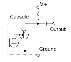
1. **Microphone Selection**: Choose an electret condenser microphone, which is commonly used for audio applications due to its sensitivity and ease of use. This type of microphone typically requires a bias voltage, which can be supplied through a resistor connected to the power supply.
2. **Biasing the Microphone**: Connect the positive terminal of the microphone to a suitable voltage source (e.g., +5V) through a resistor (typically 1kΩ). The negative terminal of the microphone should be connected to the ground. The output signal of the microphone will be taken from the junction between the microphone and the resistor.
3. **Signal Amplification**: The output from the microphone is a weak audio signal that needs amplification. An op-amp can be configured in a non-inverting amplifier configuration. Connect the output of the microphone to the non-inverting input of the op-amp. The op-amp should be powered by the same voltage supply used for the microphone. Feedback resistors (such as 10kΩ and 1kΩ) can be used to set the gain of the amplifier.
4. **Connecting the Speaker**: The amplified output from the op-amp can be fed directly to a small speaker. If the speaker requires a higher power level, a transistor can be used to drive the speaker. Connect the output of the op-amp to the base of the transistor through a resistor (e.g., 1kΩ). The collector of the transistor should be connected to the positive terminal of the speaker, while the emitter is grounded.
5. **Power Supply Considerations**: Ensure that all components are powered appropriately, and verify that the total current draw does not exceed the ratings of the power supply. Use decoupling capacitors (e.g., 10µF) across the power supply lines to reduce noise.
6. **Testing the Circuit**: Once assembled, test the circuit by speaking into the microphone and observing the sound output from the speaker. Adjust the gain of the op-amp as necessary to achieve the desired volume level.
This configuration provides a straightforward method for capturing audio input and converting it into audible output through a speaker, ideal for basic audio applications.I want to make a simple circuit with a microphone that just takes your voice and sends it to a speaker. I just want to understand how to hook up a mic.. 🔗 External reference
Related Circuits
A compact 325mW amplifier with a voltage gain of 200, suitable for use as a bench amplifier, signal tracer, or to amplify the output from personal radios. The circuit utilizes the National Semiconductor LM386 amplifier. In the schematic, the...
The circuit functions as both a latch output and a non-latched output. The control switch, labeled SB, governs the operation. When both SB and VDD are activated, the circuit enters the latch output state, allowing the sixteen output terminals...

This circuit is for an audio equalizer that is commonly found in commercial products such as high-fidelity systems, car audio, and stage equipment; however, published circuits for these devices are quite rare. This design features equalizer bands. The circuit...
Modify it to click and latch a relay when the button is pressed from anywhere in the house. Additionally, if possible, unlatch the relay when pressed again. A flip-flop circuit may be created to take the first signal and...
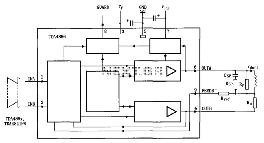
The TDA4866 is a 90-color power amplifier designed for vertical deflection systems, operating at a frequency range of 50 to 160 Hz. The CRMM circuit is implemented to ensure a high current drive input. The amplifier features a dual...
The output current of the control circuit must be amplified when the gate current needed to trigger the device exceeds the output current of the control circuit. To achieve the amplification of the control circuit output current, a suitable transistor...
Warning: include(partials/cookie-banner.php): Failed to open stream: Permission denied in /var/www/html/nextgr/view-circuit.php on line 713
Warning: include(): Failed opening 'partials/cookie-banner.php' for inclusion (include_path='.:/usr/share/php') in /var/www/html/nextgr/view-circuit.php on line 713