
Very Simple Bench Amplifier

The LM386 amplifier circuit is designed for versatility in various applications, including audio amplification for personal radios and testing equipment. The choice of the LM386 integrated circuit allows for a compact design with efficient power consumption. The amplifier's voltage gain can be tailored to specific requirements by adjusting the feedback capacitor, enabling users to optimize performance based on the application.
The circuit's input configuration is critical for ensuring that only AC signals are amplified. The DC coupling of the input can lead to undesirable outcomes if DC offsets are present, thus the addition of a coupling capacitor is advisable to block any DC component. This capacitor should be selected based on the expected frequency range of the input signal to ensure minimal signal distortion while maintaining the desired frequency response.
The use of a logarithmic potentiometer for input impedance adjustment allows for fine-tuning of the amplifier's sensitivity, making it suitable for a range of signal levels. The selection of the appropriate version of the LM386 IC is essential, depending on the required output power and load impedance, ensuring that the amplifier can drive the intended load effectively without distortion or clipping.
Overall, this LM386-based amplifier circuit offers a robust solution for audio amplification needs, with the flexibility to adapt to various input conditions and output requirements, making it an excellent choice for both hobbyists and professionals in the field of electronics.A small 325mW amplifier with a voltage gain of 200 that can be used as a bench amplifier, signal tracer or used to amplify the output from personal radios, etc. The circuit is based on the National Semiconductor LM386 amplifier. In the diagram above, the LM386 forms a complete non-inverting amplifier with voltage gain of x200. A datasheet in PDF f ormat can be downloaded from the National Semiconductor website. The IC is available in an 8 pin DIL package and several versions are available; the LM386N-1 which has 325mW output into an 8 ohm load, the Lm386N-3 which has 700mW output and the LM386N-4 which offers 1000mW output. all versions work in this circuit. The gain of the Lm386 can be controlled by the capacitor across pins 1 and 8. With the 10u cap shown above, voltage gain is 200, omitting this capacitor and the gain of the amplifier is 20.
The IC works from 4 to 12Volts DC, 12Volt being the maximum recommended value. The internal input impedance of the amplifier is 50K, this is shunted with a 22k log potentiometer so input impedance in this circuit will be lower at about 15k. The input is DC coupled so care must be taken not to amplify any DC from the preceeding circuit, otherwise the loudspeaker may be damaged.
A coupling capacitor may included in series with the 22k control to prevent this from happening. 🔗 External reference
Related Circuits
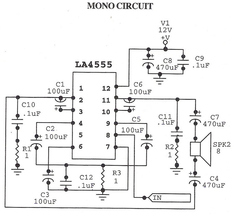
The LA4555 audio amplifier schematic includes both stereo and mono configurations. The LA4555 is primarily designed as a stereo amplifier, delivering 2.3 watts of power into 4-ohm speakers. The LA4555 audio amplifier is an integrated circuit designed for audio amplification...
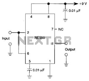
A 555 IC is configured to function as a Schmitt trigger. Inputs above and below the threshold level will turn the circuit on and off, producing a square wave output. The 555 timer integrated circuit (IC) is a versatile device...
%2BCircuit%2Bdiagram%2Busing%2BCD4047%2Band%2BIRFZ44%2Bpower%2BMOSFET.png)
This simple low-power DC to AC inverter circuit converts 12V DC to either 230V or 110V AC. By making simple modifications, it is also possible to convert 6V DC to 230V AC or 110V AC. This inverter can be...
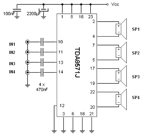
The integrated audio TDA8571J, designed for automotive applications, allows for the expansion of car radio sound or the connection of a portable MP3 player. Internally, the chip contains eight operational amplifiers set in a bridge configuration, enabling each speaker...
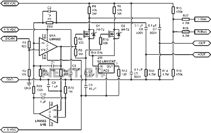
When connected to popular Stax Class 1 electrostatic headphones, the design illustrated in the figures may operate across the full audio bandwidth with a transmission voltage close to 200 Vp-p. Although the resistor divider can be modified to provide...
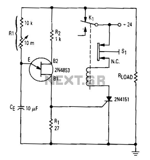
After the first cycle, the relay will normally be energized. When the normally closed pushbutton 51 is activated, the SCR turns off, the relay is de-energized, and power is applied to the relaxation oscillator and the load. After a...