
simple mixer
The output is typically biased at a midpoint voltage between the positive and negative supply voltages (ground). This midpoint is established at the non-inverting input by applying half the supply voltage through a resistor (Rin). The inverting input is biased to half voltage automatically via the output through a feedback resistor (Rf), with a blocking capacitor (Cs) preventing DC from passing through (allowing only AC signals). Capacitors are placed at the inputs and outputs of the op-amp to eliminate concerns about DC voltages used solely for internal biasing. The value of these DC blocking capacitors determines the lowest frequency point of the signal. When mixing various inputs, care must be taken to avoid signal loss due to the zero internal resistance of op-amps; thus, additional resistors (Ro) are placed in series with op-amp outputs. Each op-amp sees its Ro and the parallel combination of all Ro's from other inputs.
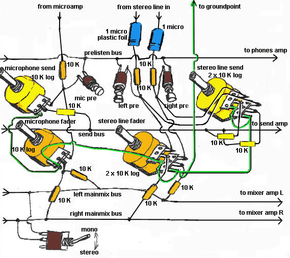
In the design, a 1 microfarad plastic foil capacitor is recommended for the input, while a 100 kOhm resistor connects the input socket to ground to prevent thumps when connecting input cables. A red resistor is included for phantom microphone supply, which is necessary for electret microphones that require additional power through the ring of a stereo mini jack. The micro preamp features a simple non-inverting operational amplifier design, necessitating a high-quality op-amp (e.g., TL 071, NE 5534, CA 3140). The design operates on a single voltage supply, thus requiring a half-supply voltage line throughout. It is advisable to place blocking capacitors (0.1 microfarad, 50V ceramic) close to each op-amp to filter noise from the voltage supply lines. For stereo or mono line inputs, no op-amp is used; instead, a resistor connects the input socket to ground and a capacitor connects the input socket to the next stage. However, incorporating a buffer stage (a mic preamp with the feedback resistor replaced by a wire) can facilitate the use of send potentiometers, offering a more compact solution.
Double op-amps can be utilized (8 pins, same price) such as NE 5532 or TL 072. The components for the send submix are highlighted in yellow; if a send submix is not required, these yellow components can be removed. For additional submix groups, replicate the yellow configurations. Faders are rotary logarithmic potentiometers, preferred over sliders for cost and performance. After the faders, equal value resistors connect all left inputs to the left summing bus and all right inputs to the right summing bus, with mono/microphone inputs connected to both buses. Pre-listening can be achieved using pushbuttons, with a simple two-pole pushbutton or a more practical three-pole pushbutton that connects to a common pre-listen line and subsequently to the headphone volume potentiometer.
Summing amplifiers amplify the combined input signals and provide impedance transformation, optimizing the output signal for amplifiers, headphones, or computers. They are constructed similarly to microphone preamps, but the feedback resistor (from pin 6 to pin 2) is typically smaller (10 kOhms), while a larger value (100 kOhms) is used for headphone amplifiers. Ground connections should be made separately to a common ground point in the stabilizer, and all voltage supply lines should also connect separately to the stabilizer. It is recommended to consider ground connections going to op-amp pins as voltage supply lines, twisting these leads together to minimize hum induction. Signal grounds should be treated similarly to input and output grounds to prevent buzz or hum. Capacitors of 10 microfarads should be polarized electrolytic capacitors rated for voltages above the supply voltage (25V is sufficient). The largest electrolytic capacitor (1000 microfarads) is part of the voltage supply stabilizer and should be rated for 35V. The power source is an external adapter providing 12V to 24V DC secondary voltage (100mA is adequate), ensuring safety by avoiding lethal voltages. The correct socket should be used, connecting the positive socket through a forward-biased diode to prevent damage from incorrect adapter connections.
The stabilizer circuit commonly employs the MC 78xx series (where xx denotes the stabilized output voltage, e.g., 12 or 18). To maximize the dynamic range of the output signal before clipping, an 18-24V DC adapter should be sought, utilizing the MC 7818 (and MC 7809 as referenced elsewhere). The op-amps require a split voltage supply, achieved by floating them at the midpoint of the stabilized supply voltage and ground using voltage divider resistors and a voltage follower (another op-amp). Alternatively, another MC 78yy (where yy equals half of xx) can be placed after the first one, although this solution may not adapt to changes in the main stabilized supply voltage. Future updates may include image files for printed circuit boards (PCBs), as constructing on perforated boards may be labor-intensive.The first two are `passive` elements and op-amp is an `active` element. Also: the first two are `two-terminal` elements and the op-amp is a `three-terminal` element. Resistor has the ability to define the current that flows through it when a voltage is applied to its terminals. Vice-versa: when a current flows through it a precise voltage drop app ears on its terminals. The simple (most frequently used) formula is: -> the first formula you read as: when a current of value I flows through a resistor of value R it produces a voltage drop of valuer U accross its two terminals. In audio mixer we use resistors to adapt the internal resistences (-> impedances) of op-amps. Also: to define the necessary voltages by `dropping` them with resistor combinations. Capacitor (in our use) is an element that blocks the DC (direct current) voltages (-> supply voltages) but lets through the AC (alternate current) voltages (-> signals).
We need DC voltage to supply the energy to the active element and to define its optimum working conditions). Also: capacitors are used to store the energy (-> we use it as such in stabiliser circuit) or to filter out the undesired AC voltages (-> we use it as such in `decoupling` the DC voltage supply lines).
Impedance is a term defining the `passive` nature of elements (the one that `consumes` the energy). For audio frequencies we can assume that resistor has only resistence and that capacitor has only capacitance. Active element also has both, but because we use the most `perfect` active element - operational amplifier, we can forget impedances and simply say: Operational amplifier is a three-terminal (input terminal, output terminal and common terminal) active (ampifying) element with infinite input resistence, zero output resistence and infinite amplification (->A).
The basic formula is: Depending of configuration op-amp can be inverting or non-inverting (-> it inverts the phase of input signal, or the output is `in phase` with the input). For such reasons it has two inputs: inverting (-) and non-inverting (+). Configuration is defined by passive elements in the `feedback loop`. Feedback loop means connecting output back to the input (-> taking part of the output signal and bring it to one of the inputs).
Two main configurations are: the output is (`biased`) at middle voltage point (`potential`) between positive supply voltage and negative supply voltage (-> here: ground). This point we define at + input of op-amp by bringing the half supply voltage to it (through Rin resistor).
The - input must also be `biased` to half voltage but this is performed automatically from teh output (through Rf resistor) and by blocking the DC path through Rs with capacitor Cs (DC current cannot pass through capacitor - therefore infinite resistence for DC but short-circuit for AC signals). - then we block all inputs and outputs of op-amp with capacitors, so that DC voltages that only serve for internal op-amp biasing do not worry us anymore.
The only thing about value of DC blocking capacitors is that it defines the lowest frequency point of signal. A formula: - when `mixing` various inputs we must take care not to lose signals from other sources because of the zero internal resistence of op-amps.
Therefore we put additional Ro resistors in series with op-amp outputs. Each op-amp `sees` his Ro and a parallel combination of all Ro`s from other inputs. Study the above picture well - there is the basic principle. capacitor at the input should be 1microfarad plastic foil, resistor 100Kohm going from the input socket to ground is to prevent a `thump` when connecting an input cable; there is a possibility for a `phantom` microphone supply - the red resistor; attention: there are electret microphones which have an additional ring -> like the stereo mini jacks - these get their `phantom` power at the ring (get a stereo input socket!) - connect the red resistor on the ring; Micro preamp is the simplest operational amplifier non-inverting design, therefore a good op-amp is needed (TL 071, NE 5534, CA 3140); the design is for single voltage supply (and op-amps are not), therefore half_the_supply voltage line is needed everywhere. also: very close to every op-amp a couple of `blocking` capacitors (0, 1microfarad 50V ceramic) are needed (to block the noise from the two voltage supply lines).
For stereo (or mono) line inputs no op-amp is used, just resistor from the input socket to the ground and capacitor from the input socket to the next (mixing, prelistening, send) stage; however, adding a `buffer` stage (-> a mic preamp with feedback resistor replaced by a wire) can make things easier with send potentiometers (-> cheaper and smaller!). Double op-amps can be used (also 8 pins/ same price! -> NE 5532, TL 072, . ). The elements for send submix are in yellow colour. If you don`t need send submix you can eliminate all the yellow elements. If you need more submix groups just replicate same ` yellow` configurations. Faders here are rotary logaritmic potentiometers (instead of `sliders` which are not cheap, or no good!), however better (more expensive) pots will serve you better, double for the stereo input control, single for the mono/ microphone control.
After faders (through equal value resistors) we connect (for the stereo inputs) all left to the left sum common strip (bus), all right to the right sum common strip and for the mono/ microphone to both (one resistor goes to left sum strip, one resistor goes to right sum strip). Prelistening can be done easiest by pushbuttons, taking the signal from before the fader - simplest solution uses just two-pole pushbutton (-> connected when pushed), more practical solution needs a three-pole pushbutton (see the picture soon!) - one pole (the middle one in three-pole) goes to (common) prelisten line (strip, bus) and further to the phones volume potentiometer.
Summing amplifiers amplify the sums of input signals and provide for the impedance transformation (from high to low) - which serves best for feeding the output signal to amplifier, headphones, computer, . Again they are build in the exactly the same manner as the microphone preamps - except the feedback resistor (going from pin 6 to 2) is about 10 times smaller -> 10Kohms.
But for phones amplifier it should be larger -> 100Kohms. Experiment with this (feedback) resistor! All connections to grounds should go separately to common ground point in stabilizer (see above) and all the voltage supply lines should also go separately to stabilizer (and again: blocking capacitors should be used with each op-amp). The best would be to think of the ground connections which go to op-amps pins 4 as voltage supply lines - complementary to the plus voltage supply line - these two leads should be `twisted` together to prevent any `hum` induction.
Grounds which go from the potentiometers are (same as input and output grounds) - `signal` grounds. Acting in this manner you prevent any possibility of `buzz` or `hum`. Capacitors of 10 microfarads are electrolitic (polarized! take care!) and they should be rated for voltages above the supply voltage -> 25V will do. Largest electrolitic capacitor is the 1000 microfarad in the voltage supply stabilizer part which should have 35 V. Just for the case! We get power from an outside `adapter` of 12V to 24V DC secondary voltage (100mA is OK), which lets us play safely because we don`t deal with lethal tensions anymore!
Just get the right socket, connect its + socket via a forward biased diode and it will be impossible to ruin the mixer with different adapters. The stabilizer circuit is the most common MC 78xx (xx = 12 or 18, which is the stabilized output voltage).
To make use of the larger dynamic range (before clipping) of output signal - find an adapter of 18-24V DC and use MC 7818 (and MC 7809 as you`ll find in the next paragraph). The op-amps need a split voltage supply, so we let them float exactly in the middle of stabilized supply voltage and ground.
This is done by voltage divider resistors and a voltage follower (again an op-amp!) or we could use another MC 78yy (yy = half the xx) just after the first one. The second one is a better solution in some ways but it does not adapt if for any reason a change in main stabilised supply voltage occurs.
And that`s all (for now). In future you may expact some image files for PCBs, because the building on the perforated board seems too much time & energy consuming. 🔗 External reference
Related Circuits
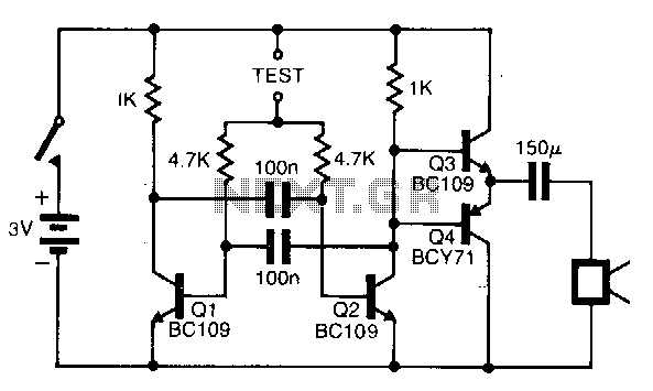
The pitch of the tone is determined by the resistance being tested. The tester can respond to resistances in the hundreds of kilohms range, while also being capable of distinguishing differences as small as tens of ohms in low-resistance...
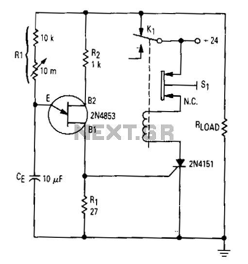
After the first cycle, the relay will normally be energized. When the normally closed pushbutton 51 is activated, the SCR turns off, the relay is de-energized, and power is applied to the relaxation oscillator and the load. After a...
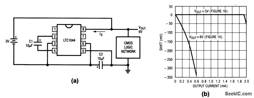
This circuit doubles the available battery voltage using an LTC1044 switched-capacitor voltage converter. It is designed to power low-power 74-CMOS (3 to 15 V) equipment for extended periods from two small 1.5 V cells. The efficiency exceeds 90% for...
This circuit was designed as a small portable DJ mixer for a friend. It is a simple audio mixer circuit featuring two dual logarithmic potentiometers to adjust input signal levels, along with several resistors for mixing. The circuit operates...
A simple water level sensor or liquid level detector for measuring or detecting a required level of water, liquid, or fluid in a tank, pool, well, aquarium, washing machine, etc. The water level sensor is an essential device utilized for...
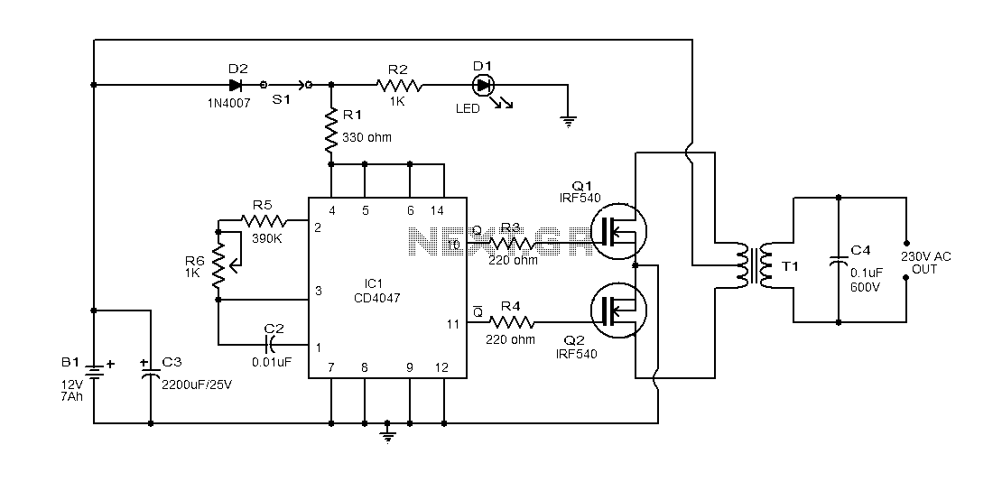
This document provides an explanation of a simple 100-watt inverter circuit using the IC CD4047 and the IRF540 MOSFET. The circuit is designed to be simple, cost-effective, and suitable for assembly on a veroboard. The CD4047 is a low-power...