
Simple mixer
The audio mixer circuit described is a passive device designed for straightforward applications in audio mixing. The use of dual logarithmic potentiometers allows for smooth adjustment of the input signal levels, providing a user-friendly interface for sound mixing. The circuit's passive nature means that it does not require a power supply, making it ideal for portable applications where power availability is a concern.
The circuit's layout includes RCA connectors for input and output, which are standard in audio applications, ensuring compatibility with various audio sources and amplifiers. The use of resistors to facilitate mixing is a common practice in passive mixers, where they serve to combine audio signals without introducing significant distortion or noise. However, it is important to note that the continuous attenuation of the signal can limit the usability of the mixer in certain scenarios. This characteristic necessitates careful consideration of the amplifier settings to achieve the desired output level.
In terms of construction, the simplicity of the circuit allows for easy assembly, making it accessible for hobbyists and those with basic soldering skills. The option to use metal enclosures for improved shielding can enhance the circuit's performance by reducing interference from external electromagnetic sources.
The design also allows for flexibility in terms of input sources; however, caution should be exercised when adding additional inputs, as this can lead to increased signal attenuation and diminished output quality. For users requiring more than a few inputs, exploring active mixer designs or incorporating an amplification stage would be advisable to maintain signal integrity.
Overall, this mixer circuit represents a practical solution for basic audio mixing needs, particularly in environments where space and budget constraints are present. The straightforward design and ease of assembly make it a valuable tool for anyone looking to experiment with audio mixing without investing in more complex and costly equipment.I designed this circuit for one friend of mine to be used as a small portable DJ mixer. The circuit is an audio mixer circuit so simple as it can be. There are two dual logarithmic potentiometers in the circuit to adjust the input signal levels and some resistors to do the actual mixing. The circuit is totally passive, so no power supply is needed . The circuit is suitable to be uses as a mixer between two line level sources and one HIFI amplifier input. This circuit have been successfully used for mixing signals form two CD players or computer soundcard and CD players.
There are many situations where simple mixer would be useful and commercially available mixer desks are too expensive and big. This simple line mixer has two drawbacks: it attenuates the signal all the time (even sliders set to maximum) and the output impedance is quite high.
The first problem can be solved by just turning a little more volume in the amplifier. High ouput impedance is no problem when connected to high impedance amplifier input with short wires (few meters). In the picture below you see the schematic of the whole mixer circuit. The potentiometer slides which are actually inside one dual potentiometers are connected together using one line.
Every input and output pin has corresponding ground signal on the right side of the signal line. You can build this circuit easily to a small plastic box using two rotary dual logarithmic potentiometers, six RCA connectors and four resistors. You don`t need any special circuit board because there are so few components that you can just solder them going from place to place.
If you want mixer which is easier to use, replace the rotary potentiometers with slider potentiometers. And if you want better shielding use metal enclosure. That line means that those potentiometers are mechanically connected together so that they move together (that line does not mean any electrical connection because it is not connected to those potentiometers).
This kind of mechanical connection is done in dual potentiometers. If you use two separate linear potentiometers then you can connect the sliders of them together using some suitable method. If you prefer totally separate left and right channel volume controls then you don`t need to do this mechanical connection between the potentiometers.
Outer part in RCA connector goes to the common ground (right tap in schematic connections). The center of the RCA connector is connected to the resistor (left tap in schematic). The ground here just tries to tell where to ground you can do it here. If you want to ground the case you can connect it here. Grounding of this circuit is not necessary. With the same resistor values you can add more inputs if you wish. Adding more inputs has some negative effects to the circuit performance, because more input you have then more attenuation this mixer circuit causes. You can use this circuit for few inputs, but if you put more than few inputs the signal level you get out of the mixer is quite fast so low that it is not usable.
If you need more than few inputs (more than three or four) then it is a better idea to use some more advanced active mixer circuit or at least add an amplifier to the signal output. If this circuit seems to be to complicated, then you can build this even simpler circuit, which mixes two signals but does not have any option for adjusting their levels.
To build this circuit you need three RCA connectors and two 10 kohm resistors (R1 and R2). The resistors connect the audio signals (center connector) from inputs together to from one output signal. You can see the wiring details in the figure below: When you have connected the audio lines together using the resistors, then connect the connect the connector grounds directly together using short piece of wire.
The answer is no. This design is so simple because this does not include this kind of fuctions. Each of those funct 🔗 External reference
Related Circuits
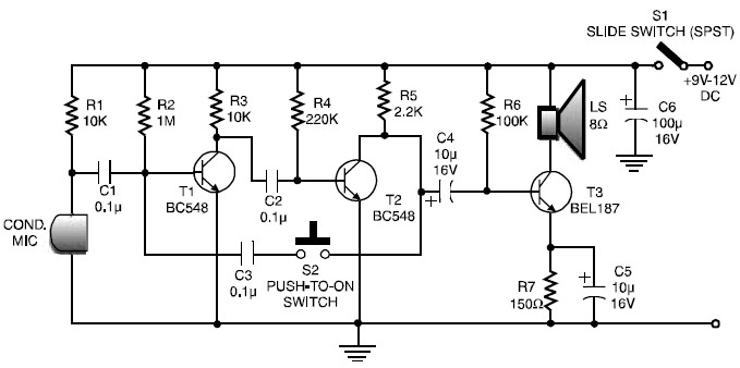
This is a low-cost and simple intercom circuit design that utilizes three transistors. Even a novice can assemble it on a piece of veroboard without difficulty. The intercom circuit is designed to facilitate two-way audio communication between two locations. The...
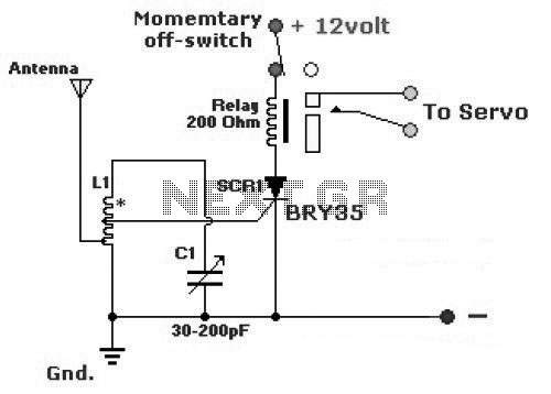
The diagram illustrates a simple and efficient receiver designed for controlling garage doors, starter motors, alarms, warning systems, and various other applications. The SCR utilized in this circuit features an exceptionally low trigger current of 30 µA. The circuit operates...
Most sound cards in computers lack stereo input for microphones, but they do have stereo inputs for high-level signals (Line). This circuit utilizes the Line input of the sound card to connect two mono microphones to the sound card's...
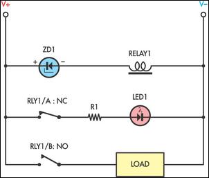
Sensitive low-current relay coils often operate at much lower voltages than their typical ratings. This can be undesirable in some applications, where low supply voltages can result in erratic system behavior. In some instances, this problem could be overcome...
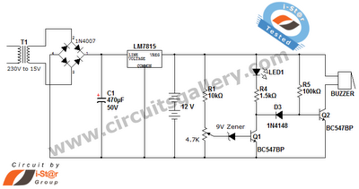
This is a straightforward 12V rechargeable smart battery charger circuit. It can be utilized as a charger for car batteries, inverter batteries, emergency light batteries, and more. An automatic indicator alarm circuit accompanies this battery charger schematic. The primary...
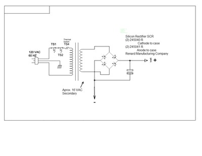
This document outlines a simple circuit diagram for a charger, utilizing a transformer, two SCRs, a capacitor, a heat sink, and a case for assembly. The circuit is designed for charging lead-acid batteries and can function even without the...
Warning: include(partials/cookie-banner.php): Failed to open stream: Permission denied in /var/www/html/nextgr/view-circuit.php on line 713
Warning: include(): Failed opening 'partials/cookie-banner.php' for inclusion (include_path='.:/usr/share/php') in /var/www/html/nextgr/view-circuit.php on line 713