
Simple AC Motor Speed Controller
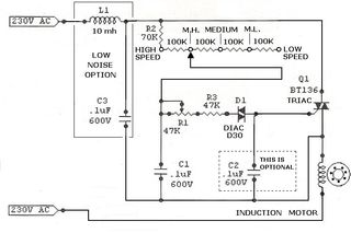
The described circuit serves as a speed control mechanism for AC motors, utilizing a combination of rectification and phase control techniques. The bridge rectifier is essential for converting the alternating current (AC) from a 120V source into direct current (DC), which is necessary for controlling the SCR (Silicon Controlled Rectifier).
The 10K ohm potentiometer allows for variable resistance, enabling the user to adjust the voltage and current flowing through the circuit. This adjustment directly influences the gate signal fed to the SCR, thus controlling the phase angle of the AC waveform applied to the motor. The inclusion of two 100 ohm resistors in the circuit may serve as current limiters or voltage dividers, ensuring that the gate of the SCR receives an appropriate signal without exceeding its maximum ratings.
The 50µF capacitor plays a critical role in filtering and smoothing the output from the rectifier, stabilizing the voltage supplied to the SCR. This capacitor also aids in reducing voltage spikes that could potentially damage sensitive components, particularly the SCR.
Diode D1 is integrated into the circuit to protect against reverse voltage spikes, which can occur when the motor is switched off or experiences sudden changes in load. This diode should be rated for at least 2 amps and possess a peak inverse voltage (PIV) rating of 600 volts to ensure reliable operation under varying conditions.
The bridge rectifier and SCR must be rated for 25 amps and 600 volts PIV, which provides a safe margin for operation, especially considering the circuit's capability to handle loads of up to 10 amps. Proper thermal management is crucial; therefore, the SCR should be equipped with an adequate heat sink to dissipate excess heat generated during operation, preventing thermal overload and ensuring longevity.
Overall, this circuit effectively combines various electronic components to achieve precise control over an AC motor's speed, making it suitable for applications such as electric drills and other variable-speed tools.This circuit will allow you to control the speed of an AC motor, for example an electric drill. The way that this circuit works is as follows. The bridge rectifier produces dc voltage from the 120vac line. A portion on this current passes through the 10K ohm pot. The circuit comprised of the 10k pot, the two 100 ohm resistors and the 50uf capacitors delivers gate drive of the SCR. The diode D1 protects the circuit from reverse voltage spikes. The ratings of the bridge rectifier and the SCR should be 25 amps and PIV 600 volts. The diode D1 should be rated for 2 amps with PIV of 600 volts. The circuit can handle a load up to 10 amps. The SCR should be very well heat sinked. 🔗 External reference
Related Circuits
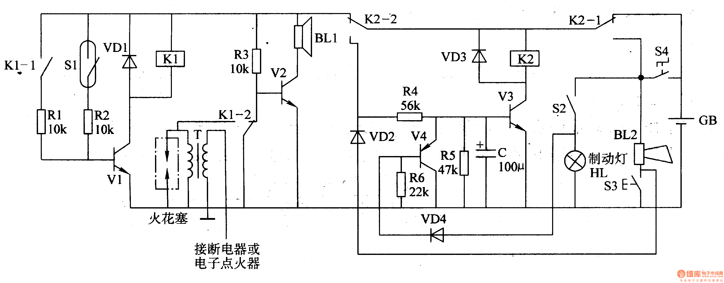
The circuit comprises a trigger circuit, an alarm control circuit, and a reset circuit for the alarm. The trigger circuit includes mercury switches (S1), a resistor, transistors (V1), and a relay (K1). The alarm control circuit is made up...
A small scroll saw is intended to be equipped with a cost-effective speed controller. The saw operates using an AC motor that seems to be brushless based on the examination conducted during disassembly. To design a speed controller for an...
An increasing number of appliances draw a very small current from the power supply. When designing a mains-powered device, one can typically choose between a linear power supply and a switch-mode power supply. However, if the total power consumption...
In certain applications, it is crucial to allow a motor to operate in only one specific direction, even when the power supply phase sequence is incorrect. This situation may arise due to external factors, such as incorrect wiring after...
As high-performance microprocessors require increased power in automotive multimedia and telematics, commonly referred to as infotainment products, several well-known issues arise, including noise susceptibility, electromagnetic interference (EMI), and loop compensation, among others. Average current-mode control (ACMC) assists in mitigating...
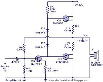
The initial section of the circuit is a preamplifier that utilizes transistor Q1 (2N2222). The collector of transistor Q3 is connected to the base of transistor Q2 (2N2905A), which creates a complementary symmetry pair with Q3 (2N3053). The amplified...