
Simple 12V to 24V DC DC converter using LM324 and transistor

The described circuit utilizes the LM324 operational amplifier as the core component for the boost converter functionality. This circuit is designed to convert a 12V input voltage to a 24V output voltage, making it suitable for applications that require a higher voltage supply from a lower voltage source.
The operation of the boost converter is based on the principle of energy storage and release, utilizing an inductor to store energy when the switch is closed and releasing it to the output when the switch is opened. In this configuration, the LM324 serves as a voltage regulator and control circuit, ensuring stable operation and maintaining the desired output voltage.
Key components of the circuit include the LM324, an inductor, a diode, and capacitors. The inductor is selected based on the desired output current and voltage ripple requirements, while the diode must be rated for the output voltage and current to prevent reverse current flow. Capacitors are used at both the input and output to filter voltage fluctuations and stabilize the output.
The feedback mechanism is implemented using resistors connected to the non-inverting input of the LM324, allowing the circuit to adjust the duty cycle of the switching element based on the output voltage. This feedback loop is crucial for maintaining a steady output voltage of 24V, even with variations in load or input voltage.
Overall, this boost converter circuit is effective for applications requiring a reliable 24V power supply from a 12V source, capable of delivering up to 800mA of output current. The simplicity of the design, combined with the performance characteristics of the LM324, makes it an attractive solution for various electronic projects and systems.A simple 12V to 24V dc dc converter circuit with diagram built around LM324. This boost converter with schematic can provide up to 800mA output current and a steady 24V DC.. 🔗 External reference
Related Circuits
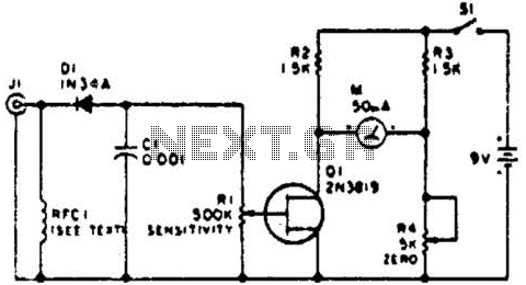
This circuit employs a FET as a DC amplifier within a bridge configuration. Resistor R4 is adjusted for meter nulling with switch J1 short-circuited. Any surplus 50-mA meter can be utilized in this circuit. RFC1 represents a suitable RF...
This is a simple, low-cost 50W off-line switching power supply designed for home projects or for learning about the operation of flyback converters. It operates over a universal AC input range of 90-264 VAC and provides a 12V DC...
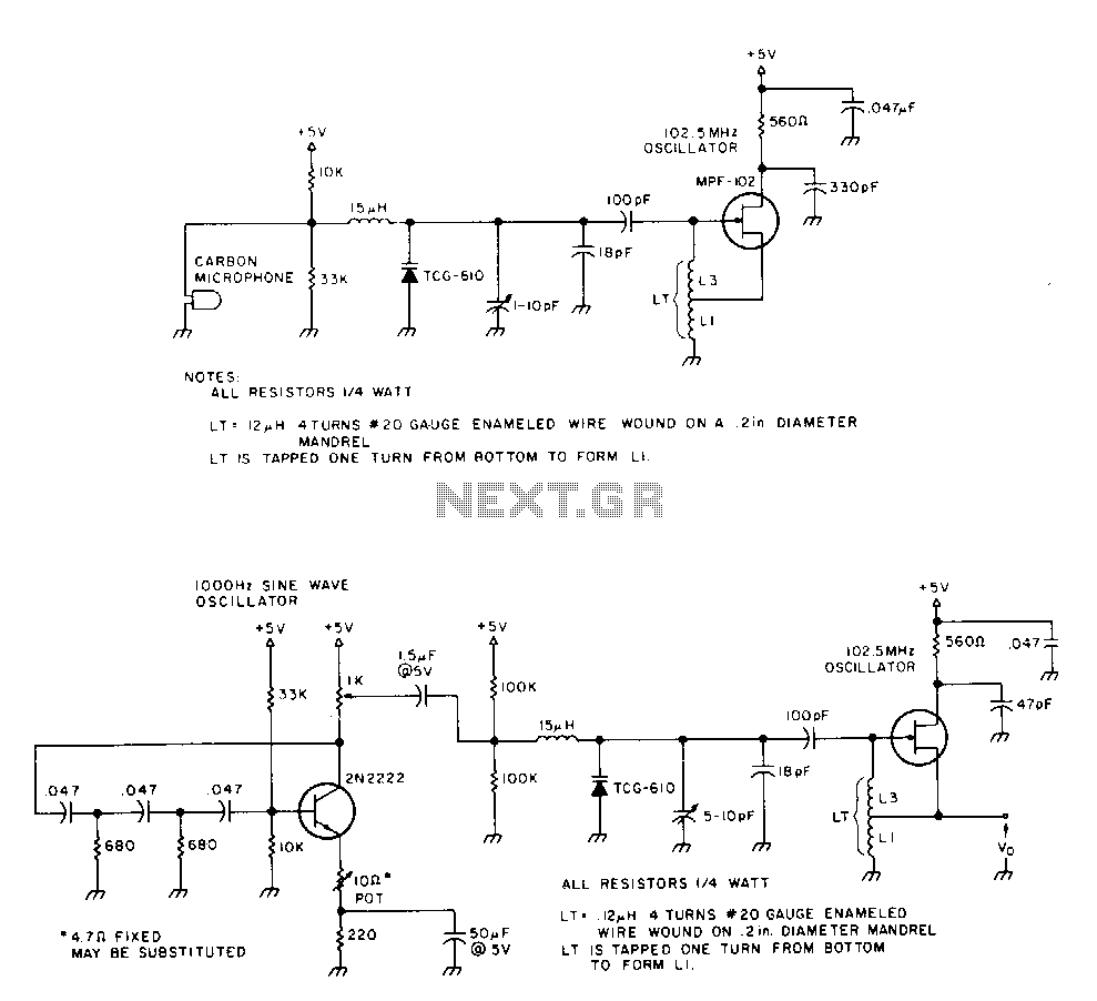
The 2N2222 circuitry is a three-element, phase-shift oscillator circuit designed to produce a 1,000 Hz sine wave. This sine wave is applied to the TCG-610 varactor diode, which has a capacitance of 6 pF at 4 V. This application...

Generating sine waves with controlled frequencies over a wide range is challenging when using RC or LC sinusoidal oscillators. However, this can be effectively achieved using a wideband digital square wave oscillator, a counter, and a weighted summing network....
The circuit was designed to provide an adjustable power supply that is symmetrically configured, offering a voltage range from 1.25V to 30V at a current output of 1A. The adjustable power supply circuit is typically composed of several key components...
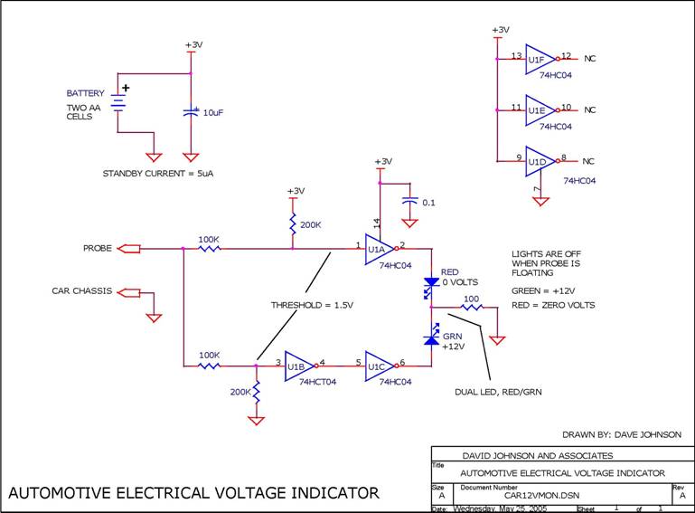
When troubleshooting the 12V electrical system of an automobile, it is beneficial to have a simple voltage indicator tool instead of a voltmeter. This electronic circuit is powered by two AA batteries or two N cells, providing sufficient energy...