
Simple One-Wire Touch Detector circuit
The described circuit operates based on the principle of capacitive touch sensing. When a user touches the metal plate, it alters the capacitance at that point, which influences the voltage across the voltage divider formed by resistors R1 and R2. This change in voltage is detected by the input of the Schmitt trigger gate, which has a hysteresis characteristic that provides a clean transition between the high and low states.
The output of the Schmitt trigger can be used to drive various loads, such as relays or microcontrollers, allowing for a wide range of applications. The inclusion of a capacitor in the circuit serves to filter out any high-frequency noise, ensuring stable operation. LED1 provides a visual indication of the circuit's activation state, while resistor R3 limits the current flowing through the LED to prevent damage.
Overall, this circuit design is compact and versatile, making it suitable for various electronic projects that require touch activation or sensing capabilities. Proper selection of resistor values and the capacitor will ensure optimal performance and responsiveness of the touch-sensitive feature.This simple circuit can be used to activate whatever you like, for example, by connecting it to microcontroller, relays, secret alarms, robot applications or just turn on LED1 which lights up as long as you touch the metal plate. The circuit consists of voltage divider R1 and R2, one Schmitt trigger/inverter gate from a 40106 IC, a small capacitor to keep strong RF at bay and LED1 with current limiting resistor R3.
The metal plate is connected via a wire to R1. R1 and R2 together form a voltage divider.. 🔗 External reference
Related Circuits
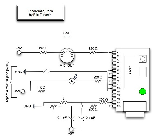
A few nice MIDI controller interfaces were discovered. The Knee(Audio)Pads are a wearable MIDI device. The MIDI controller interfaces mentioned provide innovative solutions for music production and performance. The Knee(Audio)Pads, in particular, represent a unique advancement in wearable MIDI technology....
This is a simple game circuit designed for multiplayer enjoyment. The objective is to score one hundred points within a limited timeframe. To restart the game, the S1 button switch must be pressed. It is important to ensure that...
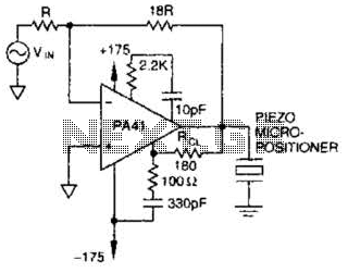
The PA41 from Apex Microtechnology is utilized to drive a piezoelectric micropositioner. The drive voltage is less than 20 V peak-to-peak at the input. The PA41 is a high-performance power amplifier designed specifically for driving piezoelectric devices, which require precise...
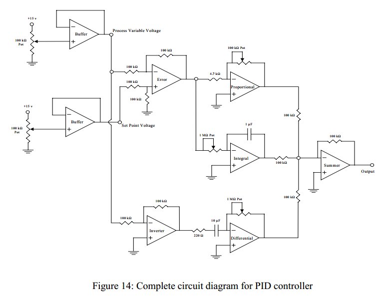
Convert a feedforward operational amplifier PID loop to C code. Assistance is needed for this conversion, as the process is unfamiliar. Input values can be obtained through an ADC, such as voltage or current, but coding a feedforward PID...
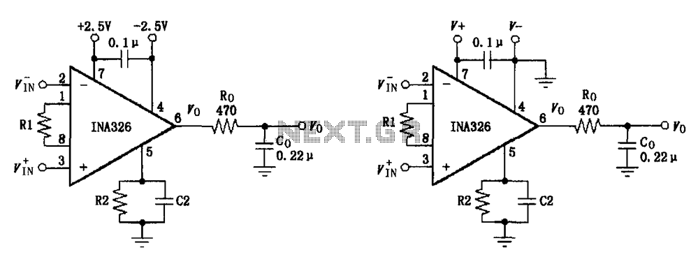
The basic connection circuit for the INA326/327 includes signals and power. A 0.1 µF capacitor is selected for power supply filtering and should be placed as close to the chip's supply pin as possible. Ro and Co serve as...

Driving a D/A converter using an A/D converter provides an overall analog-hold function. Although this function has limitations in output resolution, it offers zero voltage droop and infinite hold time. The A/D converter depicted (IC1) features a 12-bit compatible...