
Simple TV Transmitter circuit diagram (VHF)
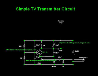
The circuit diagram described facilitates the transmission of television signals over moderate distances, making it suitable for various applications, such as local broadcasting or experimental setups. The choice of the BC 108 transistor is critical for achieving optimal performance, as it can handle the required frequency range and provide adequate amplification.
When constructing the inductor L1, the specifications regarding the number of turns and wire gauge are crucial for tuning the circuit to the desired frequency. The use of #24 enameled wire is recommended for its balance between resistance and inductance, which influences the overall efficiency of the transmitter. The air core inductor design allows for a lightweight and compact solution, essential for portable or DIY applications.
For those unable to source the specified transistor, alternatives like the BC337, 2N2222, or BC546 are suitable substitutes, each offering similar electrical characteristics. This flexibility ensures that builders can complete their projects without being hindered by component availability.
In summary, this circuit diagram serves as a practical guide for individuals interested in TV transmission technology, providing essential details on component selection and construction techniques to achieve successful signal transmission.Most of people ask TV transmitters. So Today I`m going to give you a very useful circuit diagram. By using this circuit you can send your signals 75m to 100m. This circuit diagram is not my own circuit one of my friends gave me this. I suppose you guys also can send your own circuit diagrams for us. Then we can publish them through our website. Here The y have used common transistor BC 108 If you are unable to find this transistor you can use equal transistors like Bc337 2n2222 Bc 546 # To make L1 wound 6 turns of #24 enameled wire on a 10mm air former for frequency 60 - 80 MHz For 150 - 180 MHz wound 4 turns and for 180 - 200MHz wound 2 turns. 🔗 External reference
Related Circuits
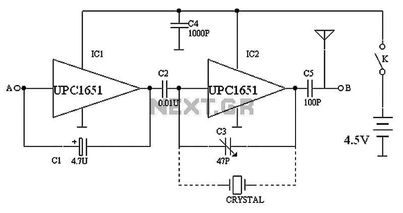
The circuit depicted in the figure includes IC1 and C1, which form a low-frequency oscillator operating at approximately 400 Hz. IC2 and C3 are configured to create a frequency oscillator around 37 MHz. The low-frequency signal is output from...
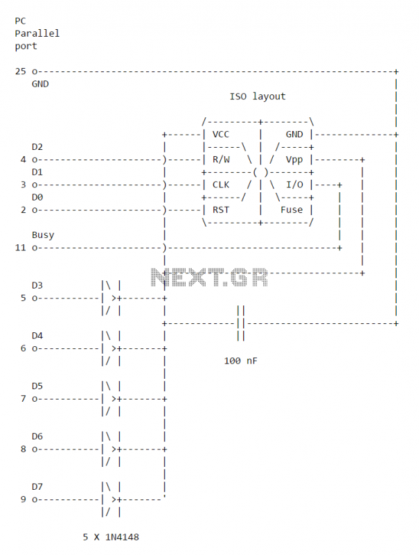
This simple PC Smartcard reader was shown in Electronics Design magazine February 17, 1997 issue on page 172 in the ideas for design section. The circuit is designed by Jose Carlos Cossio and is based on simple smartcard reader...
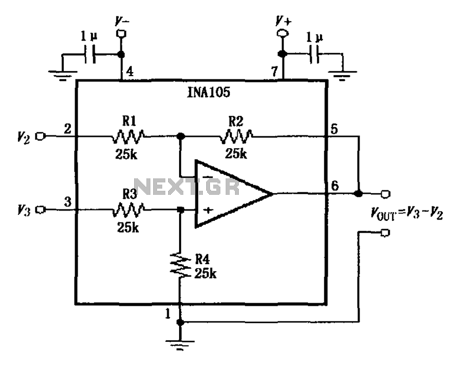
The power supply terminal should utilize a 1 µF chip capacitor filter, positioned as close as possible to the chip's supply pin. The signal is generated by the input pins 2 and 3. The source resistance of the signal...
This is a simple 1.5V powered LED flasher circuit diagram. This circuit can flash 1.7V or 2.3V LEDs (depending on the color) using a 1.5V DC input. The LED will turn on when the 100µF capacitor is charged by...
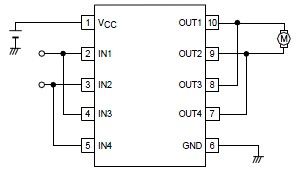
A simple forward-reverse motor control driver electronic circuit can be designed using the LB1948M, a two-channel low saturation voltage forward-reverse motor control driver IC. The LB1948M motor driver is suitable for use in 12V system products and can drive...
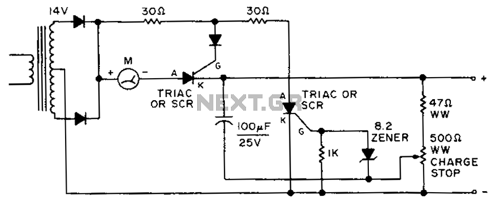
By adjusting the circuit with a 500-ohm resistor, the resistor is integrated into a fully charged battery system. The circuit described involves a 500-ohm resistor that plays a crucial role in regulating the operation of a fully charged battery system....