
Simple metal detector with 4011
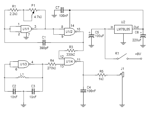
The metal detector circuit utilizes a CD4011 quad 2-input NAND gate IC (U1) as the core component for generating oscillators and processing signals. The circuit is designed to operate at a reference frequency of approximately 250 kHz, which is established using two of the NAND gates (U1/1 and U1/2). The capacitors (C1) and resistors (R1) work in conjunction with a linear potentiometer (P1) to fine-tune the oscillator frequency. This configuration allows for a variable frequency output that can be adjusted to achieve a "zero beat" condition when no metal is detected.
The search oscillator is constructed using the third NAND gate (U1/3) and is connected to the search coil (L1), which is wound with 14 turns of AWG 26 wire. This coil acts as the sensing element of the detector. The output from the search oscillator is mixed with the reference oscillator output at the fourth NAND gate (U1/4), which functions as a mixer. The mixed output is then filtered by capacitor C4 to remove unwanted high-frequency components, allowing only the desired audio frequency to pass through.
The audio output is intended to be connected to headphones via a headphone jack (J1), which can accommodate either a 1/4 inch or 1/8 inch connector. The user can listen to the audio tone that varies with the presence of metallic objects. As the search coil approaches a metallic object, the tone will change in pitch, providing an audible indication of the object's size and proximity.
Power supply regulation is achieved using an LM78L05 voltage regulator (U2), ensuring that the circuit operates at a stable 5V, which is critical for the reliable performance of the CMOS IC. The remaining components, including various resistors (R3, R4, R5) and capacitors (C2, C3, C5, C6, C7), serve to stabilize the circuit, filter power supply noise, and set the appropriate time constants for the oscillators.
Due to its simplicity and use of readily available components, this metal detector is a practical project for hobbyists and beginners. However, it is important to note that the detection capability is limited to relatively large metallic objects at short distances, and it may not perform as effectively as more sophisticated commercial metal detectors.This simple metal detector requires only a handful of components and an evening's work. Built around a cmos4011 IC, is very robust and versatile. The 250 kHz reference oscillator is built with two gates (U1/1 and U1/2), C1, R1 and P1. The search oscillator uses only one gate (U1/3), two capacitors and the search coil. The outputs of the two oscillators are fed to the fourth gate acting as a mixer and filtered with C4. After assembly, connect the headphones and slowly turn P1. The pitch will get lower until it disappears. Continuing to rotate P1 in the same direction will cause the pitch to rise again. The point at witch the pitch is the lowest and disappears is called "zero beat". If you can not get this zero beat frequency for the entire turn of P1 you may have to select different values for C1. Turn P1 close to the zero beat position, then move the search coil near a metallic object. The tone should change, depending on the size and distance of the metal. Note that this simple detector's performance is not comparable to more advanced commercial products. It will only detect relative large metallic objects at a short distance. Coins and other small objects will be much harder to find! Parts list: U1: CD4011 (Quad 2-input NAND Gate) U2: LM78L05 (5V Regulator IC) R1: 2.2k 5% resistor R3: 330k 5% resistor R4: 270k 5% resistor R5: 1k 5% resistor C1: 390pF NPO capacitor C2, C3: 10nF C4: 100nF C5: 100uF/16V electrolytic C6: 220uF/16V electrolytic C7: 100nF ceramic P1: 4.7k lin.
potentiometer L1: 22cm diameter, 14 turns, AWG 26 K1: SPDT toggle switch J1: Headphone jack 1/4 or 1/8 inch 🔗 External reference
Related Circuits
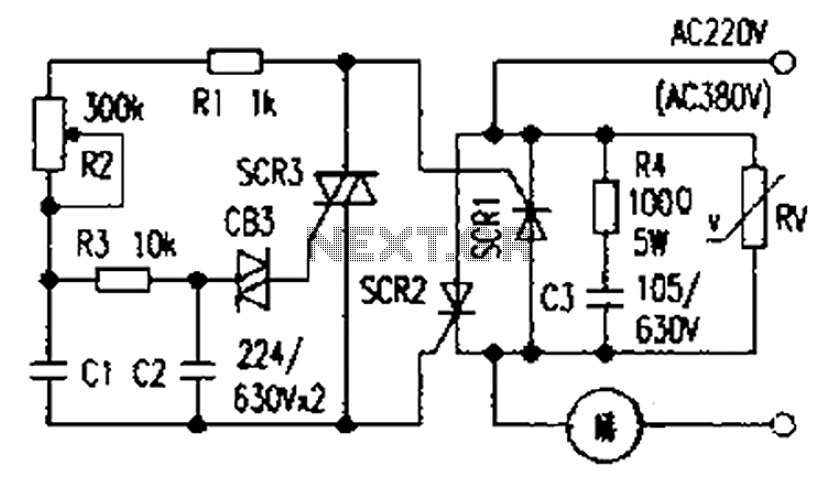
The presentation of a general power thyristor trigger circuit is more complex, and some components are difficult to procure. A successful trigger circuit has been constructed for only a few dollars. This circuit is designed to trigger a thyristor...
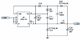
The following file is an application note describing the two stages of an electronic ballast for a 250 W HID metal halide lamp. The components include. The application note outlines a two-stage electronic ballast designed specifically for a 250 W...
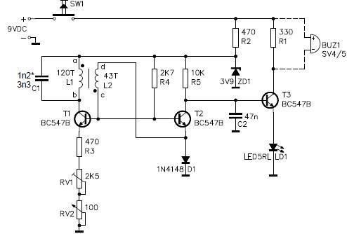
This metal detector circuit project is a simple design based on common electronic components. It utilizes transistors to provide a visual indication through an LED and an acoustic signal to alert users when metal is detected. To calibrate the...
The preamp featured has optional tone and balance controls which may be omitted if desired. The input switching may be extended if needed to accommodate more signal sources. In this version, no RIAA (phono) input is provided. See the...
This schematic diagram illustrates a water level sensor, detector, and monitor circuit. An alarm is also integrated into this circuit. It is designed to detect any fluid with a resistance below 900K ohms. The water level sensor circuit typically employs conductive...
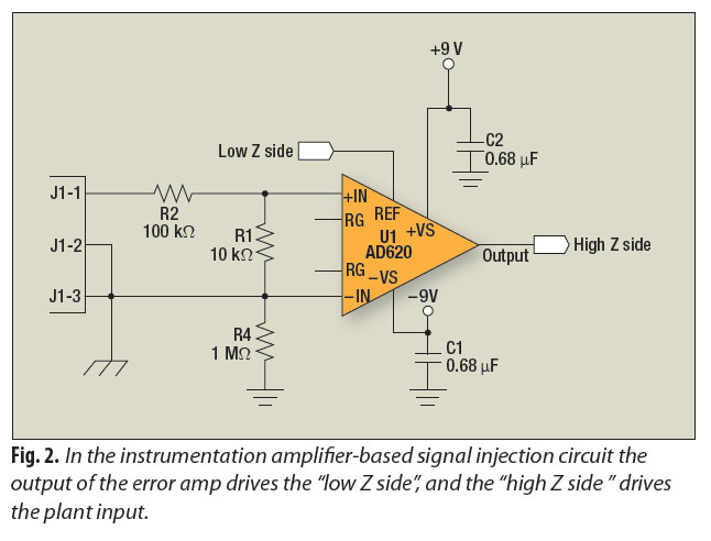
A signal-injection circuit for control-loop analysis is flat from DC to 200 kHz, isolated from chassis ground, and easily constructed with a readily available instrumentation amplifier. The signal-injection circuit is designed to facilitate control-loop analysis by providing a stable and...