
Motor Controller
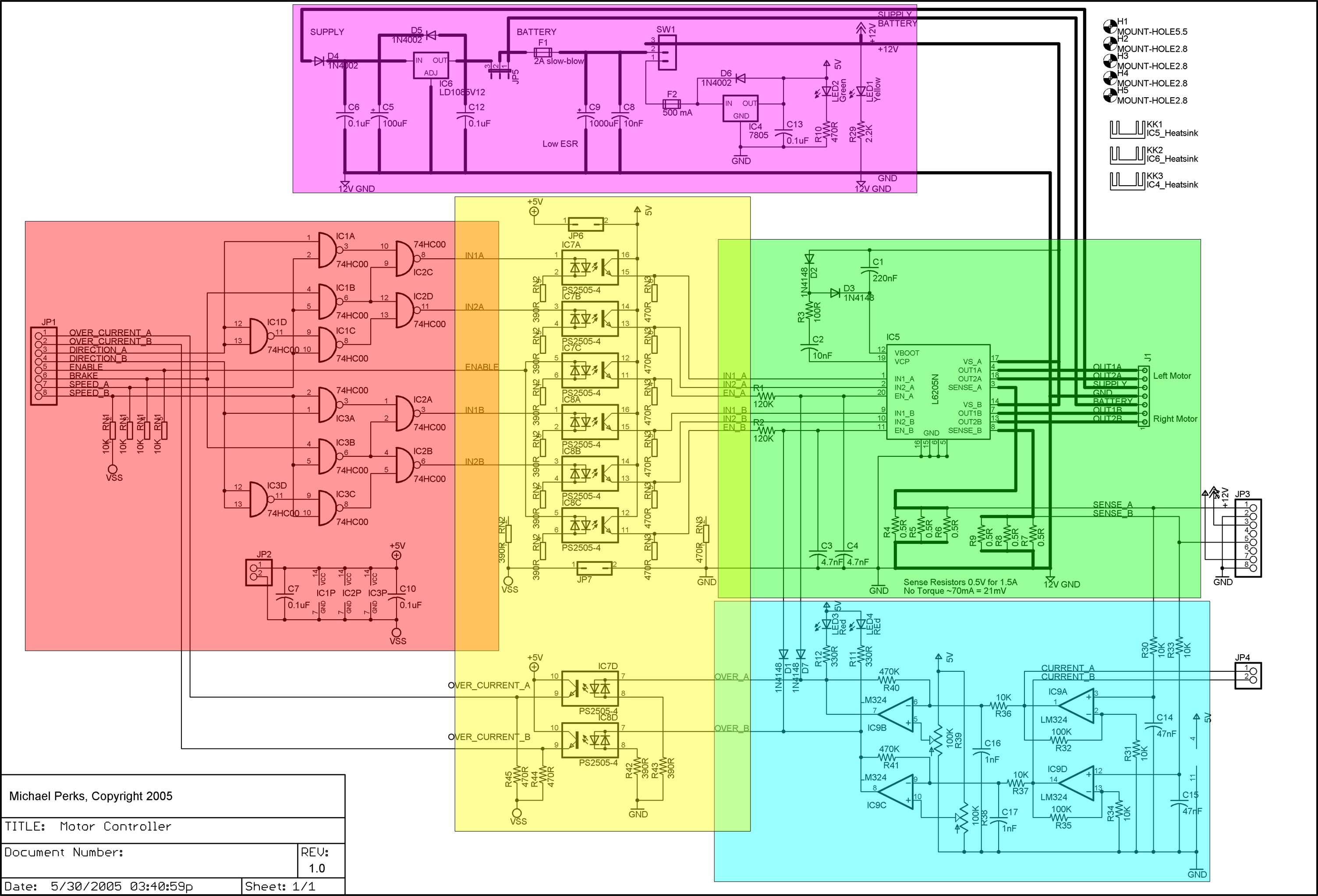
Although the motor controller utilizes a specific H-bridge driver chip, its modular design allows for the integration of one or more modules into custom motor controller circuits. Driver chips vary primarily in power rating, the capability to drive one or two motors, and packaging types. Higher-end models include additional driver logic, thermal shutdown, and over-current protection. Notable examples are the National Semiconductor LMD18200 and the SGS-Thomson (ST) Microelectronics L298, which have specialized packaging. For applications requiring lower power and functionality, the ST Microelectronics L293D and the pin-compatible Texas Instruments SN754410 in DIP packaging are suitable alternatives.
The L6205 from ST Microelectronics was selected for its similar power capacity and more accessible DIP packaging, making it easier for prototyping on a breadboard. The L6205 is a DMOS dual full bridge motor controller in a 20-pin DIP package capable of driving up to 2.8 Amps (5.6 Amps when paralleled). With the choice of the H-bridge driver chip established, the remaining motor controller circuitry could be designed. The complete circuit diagram includes color-coded areas for each sub-module, with detailed descriptions and parts lists for each section provided. The EAGLE schematic and stripboard layout are available for download.
The power regulation circuit, depicted in purple on the circuit diagram, accommodates power from either a wall wart or a 10-cell rechargeable NiMH battery. It features two regulators for 12V and 5V outputs, each monitored by an LED. Thicker connectors denote circuits carrying voltages exceeding 5V, capable of handling higher currents for motor operation. A DPDT on/off switch allows for the selection of either 5V or both 5V and 12V outputs. When the jumper (JP5) is set to the 12V regulator position and the switch is off, it has been observed that the 12V regulator continues to draw some current, necessitating an additional master on/off switch.
Power is supplied from a 13-20V wall wart to a low dropout 12V regulator rated at 3A, which requires heatsinking due to significant heat generation when driving 12V motors. A jumper (JP5) is also employed to select between the regulated 12V or approximately 12V from the battery, which, when fully charged, can exceed 12V without causing issues. A high-amperage fuse (2A) is incorporated to protect the rest of the circuitry.A dual DC motor controller that utilizes an H-bridge controller chip. As well as the basic features of the H-bridge driver chip including thermal and over-current protection, the circuit presented in this project supports dual 12V/5V regulated power supplies, sign/magnitude and brake driver logic, current sensing and optional opto-isolation of the 5V logic and 12V motor driver circuitry. Although the motor controller uses a particular H-bridge driver chip, the modular design of the overall motor controller means that it is possible to use one or more of the modules with your own motor controller circuit. Most of the driver chips tend to fall into the last category. The fundamental differences between various driver chips are their power rating, ability to drive 1 or 2 motors and the packaging.
Higher-end chips also have additional driver logic, thermal shutdown and over current protection. The most popular chips are the National Semiconductor LMD18200 and the SGS-Thomson (ST) Microelectronics L298 but they have specialized packaging. With less power capacity and less function are the ST Microelectronics L293D and the pin compatible Texas Instruments SN754410 that have DIP packaging.
I investigated various prebuilt motor controllers circuits based on the L298 and LMD18200 but in the end I decided to have the experience and satisfaction of building my own circuit. My initial choice for a motor controller was the L298 but then I found another controller from ST Microelectronics that has a similar power capacity but is in DIP packaging which makes it easier to breadboard.
This chip which can be considered as a L293 on steroids is the L6205 and is part of a family that also includes the L6206 and L6207. To summarize the L6205 datasheet ; it is a DMOS dual full bridge motor controller in a 20 pin DIP package that can drive up to 2.
8 Amps (5. 6 Amps if paralleled). Having decided on the H-bridge driver chip, then the rest of the motor controller circuitry could be designed. The next section gives the schematic and design details for each of the sub-modules in the complete motor controller.
Principles in this design could also be applied to your application. Below is the complete circuit diagram ( click to get a larger image) with color-coded areas for each of the sub-modules. Each sub-module is described in a section below and a parts list for just that sub-module is also given.
The complete EAGLE schematic and stripboard layout is also available for download. The purple area in the circuit diagram below is for the power regulation circuit. This sub-module allows for power from either a wall wart or a 10 cell rechargeable NiMH battery. There are two regulators for 12V and 5V outputs and LED monitors for each one. The thicker connectors show the circuits that carry voltages that are not 5V and may also carry heavier currents for driving the motors. A DPDT on ‘off ‘on switch can be used to either select just 5V or both 5V and 12V. When JP5 is in the 12V regulator position (pins 2 and 3 jumpered) and the switch turned off, I found that the 12V regulator was still drawing some current so an additional master on-off switch is also needed.
Power from a 13-20V wall wart is fed to a low dropout 12V regulator that a 3A rating. Heatsinking of this regulator is a must as it can get quite warm when driving 12V motors. A jumper (JP5) is used to select either the regulated 12V or approximately 12V from the battery. At full charge the battery can put out more than 12V but I haven`t seen a problem with this. A high amperage fuse (2A) is used to protect the rest of the circuitry. This is also the point where 🔗 External reference
Related Circuits
Connection of a drive and a two-phase hybrid stepper motor using a four-wire system, with the motor windings configured in both parallel and series connections. This method allows for high-speed performance, although it requires a large drive current (1.73...
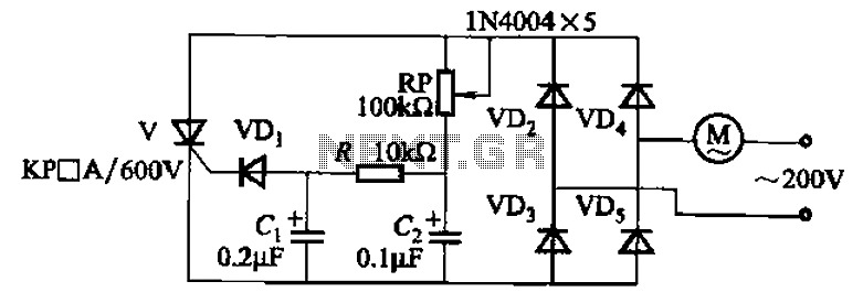
The circuit illustrated in Figure 3-11 employs a unidirectional thyristor control mechanism. An adjustable potentiometer, designated as RP, is utilized to continuously modify the motor speed. The circuit utilizes a unidirectional thyristor, also known as a silicon-controlled rectifier (SCR), which...
Camping today often requires carrying various electronic devices for daily activities and entertainment. Typically, a charged lead-acid battery and a power inverter are utilized to ensure a well-organized trip, allowing family members to use their electronic devices comfortably. It...
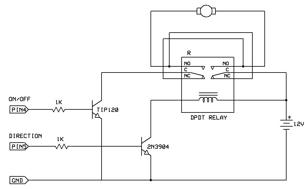
One of the simplest methods to enable a motor to rotate in both directions is by utilizing a double-pole, double-throw (DPDT) relay. This setup requires two transistors and two Stamp pins: one for on/off control and the other for...
Due to its high amplification factor and integrated power-output stage, an integrated power operational amplifier serves as an effective driver for AC motors. One operational amplifier can be configured as an oscillator to generate the necessary AC signal. The...
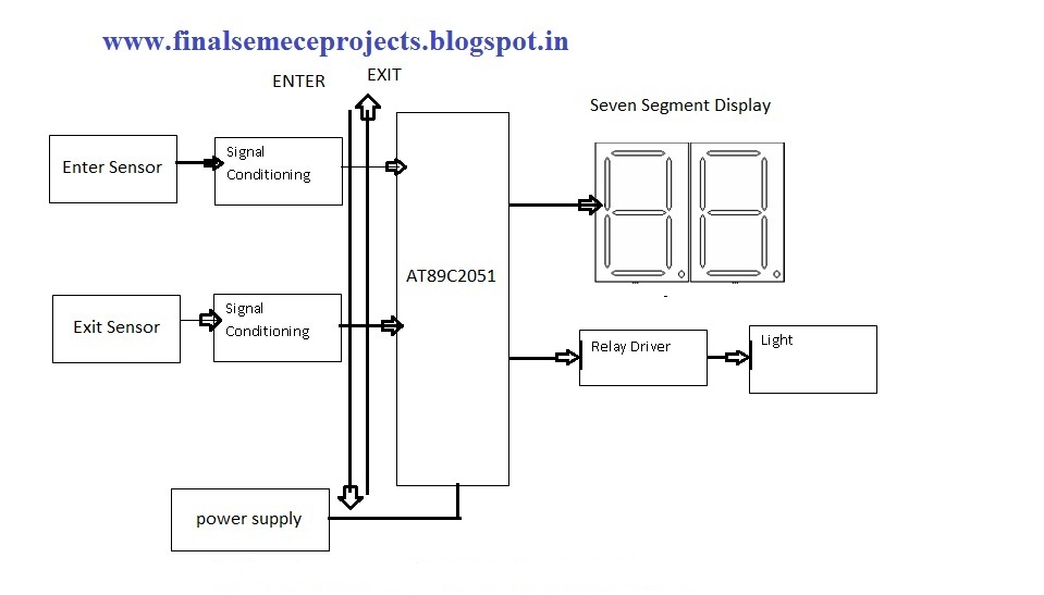
This project involves an automatic room light controller with a bidirectional visitor counter using a microcontroller. It is designed to manage room lighting and accurately count the number of individuals present. When a person enters the room, the counter...