
dome light dimmer cars
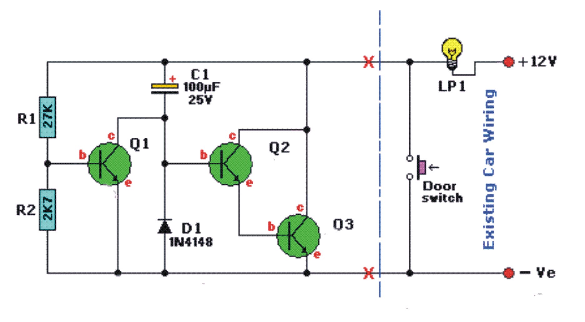
A typical dome light dimmer circuit for automotive applications operates using a combination of a capacitor, resistor, and a diode to control the illumination and dimming of the light. The circuit is designed to sense the state of the door switch and adjust the light accordingly.
When the car door is opened, the door switch closes, allowing current to flow and charging capacitor C1. This capacitor stores energy and will keep the light illuminated at full brightness. The charging time will depend on the values of the capacitor and any resistors in the circuit. A larger capacitor will take longer to charge but will also provide a longer illumination time.
Once the door is closed, the door switch opens, and the capacitor C1 begins to discharge through the resistor and diode D1. The resistor controls the discharge rate, which in turn affects how quickly the light dims. A resistor value of 25 ohms is suggested to limit the current flowing through the circuit to a safe level, preventing damage to components such as the diode. The diode (1N4148) is positioned to allow current to flow in one direction, protecting the circuit from reverse polarity.
In this setup, it is crucial to ensure that the diode can handle the peak current when the door is opened. The 1N4148 diode is rated for 450 mA, which is adequate for most dome light applications, but care should be taken to ensure that the total current draw does not exceed this rating. The circuit can be simplified by using a microcontroller or dedicated automotive light dimmer IC that can provide more precise control over the dimming function and additional features, such as programmable dimming times or integration with other vehicle lighting systems.
To connect the circuit directly to the door switch, the switch can be wired in series with the capacitor and resistor. This configuration will allow the circuit to operate as intended, with the light illuminating upon opening the door and gradually dimming when the door is closed. Proper attention should be given to the ratings of all components used in the circuit to ensure reliable operation within the automotive environment.Any idea where can I get the schematics for the dome light dimmer to be used in car. Which means that when I open the door, the light will light up and when closed, the light will slower dim and off. Thank you for the reply, how would I connect the circuit if I want to connect directly to the door switch The circuit given in is kinda complicatin
g and wouldn`t the light just light up if the switch is on Please advice. The first link shows all the door switches and a selector switch to determine which means, if any, to turn on the light. The text below explains it all. The second link simplifies it all. To answer your question, yes the light will be on full brightness as long as door is open. When the door is closed, C1 eventually gets up to 12 V. When the door is opened, C1 is discharged through the switch and D1. There is no current limit in this circuit, so the current will be quite large. A 1N4148 is only rated at 450 mA peak, so the circuit should really have at least 25 © in directly series with C1.
🔗 External reference
Related Circuits
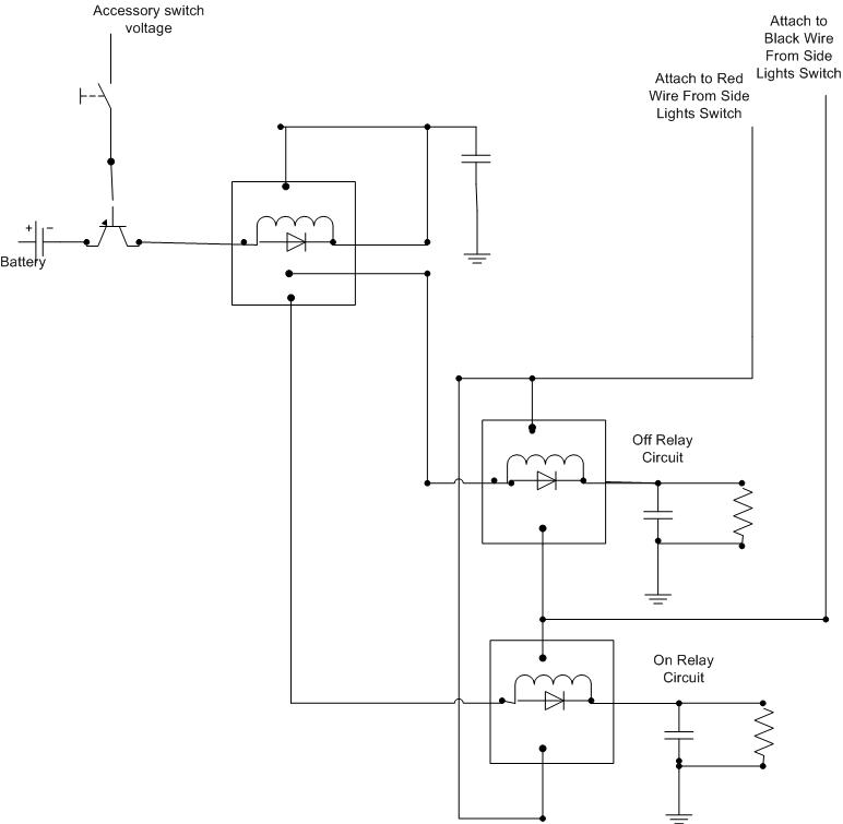
A decision has been made to install daytime driving lights for an Elise vehicle. The intention is to eliminate the need for manually pressing the button on and off repeatedly. The installation of daytime driving lights (DRLs) enhances vehicle visibility...
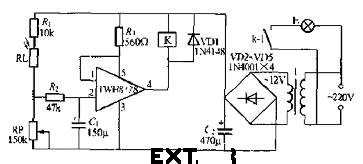
Automatic lights using a light sensor, the TWH87SL power switch integrated circuit consists of a first input terminal TWH8751 connected to the positive terminal of the power supply. The output pin state is determined by the strobe terminal, which...

This page features a circuit that has twenty open collector outputs that turn on one at a time in a continuous sequential manner. The circuit utilizes the 74LSxx family of TTL integrated logic devices. The circuits are designed to...
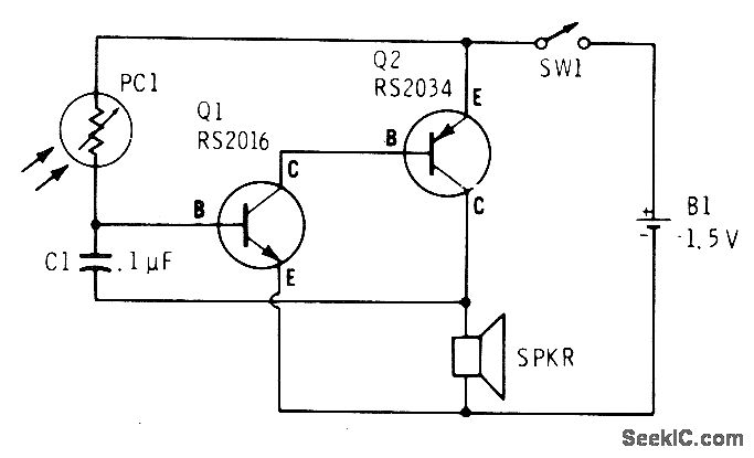
A low light condition on a cadmium sulfide photocell (Radio Shack 276-116) generates a series of clicks in a miniature 8-ohm loudspeaker. As the light intensity increases, these clicks coalesce into an audio tone that escalates in frequency with...
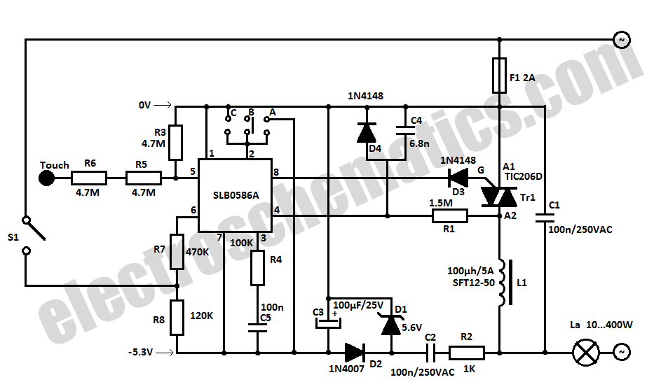
The SLB0586A integrated circuit from Siemens can be utilized to create a simple touch light dimmer circuit, allowing for the adjustment of lamp intensity. When paired with a TIC206D triac, this setup enables smooth regulation of light intensity for...
An efficient automatic solar garden lights circuit with minimal components. The notable feature is that it operates entirely automatically, with the solar panel functioning as a light detector. The automatic solar garden lights circuit is designed to provide illumination in...