
Simple Radio Circuit using Op Amp
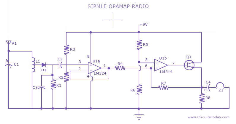
The presented radio circuit schematic utilizes an operational amplifier (op-amp) to create a cost-effective and straightforward radio receiver. The core functionality of the circuit revolves around the op-amp, which serves as a sensitive audio amplifier, capable of amplifying incoming radio frequency (RF) signals.
The circuit typically includes several key components: the op-amp itself, resistors, capacitors, and possibly an inductor or transformer for tuning purposes. The input stage of the circuit is designed to capture RF signals from an antenna. The antenna can be a simple wire or a more sophisticated design, depending on the required range and sensitivity.
In the circuit, the op-amp is configured in a non-inverting amplifier configuration, which allows for high input impedance and low output impedance, making it ideal for signal amplification. The gain of the amplifier can be adjusted by changing the feedback resistor values, which allows for flexibility in handling varying signal strengths.
Capacitors are used in the circuit to filter out unwanted frequencies and noise, ensuring that only the desired audio frequency signals are amplified. Additionally, a tuning circuit may be incorporated using an inductor and variable capacitor to allow the user to select specific radio stations by adjusting the resonant frequency of the circuit.
Overall, this low-cost radio circuit schematic is an excellent project for beginners in electronics, providing hands-on experience with op-amps and basic radio technology while demonstrating fundamental principles of signal amplification and tuning.A low cost,simple radio circuit schematic using op amp.This radio circuit diagram consists of a sensitive audio amplifier which receives strong signals.. 🔗 External reference
Related Circuits
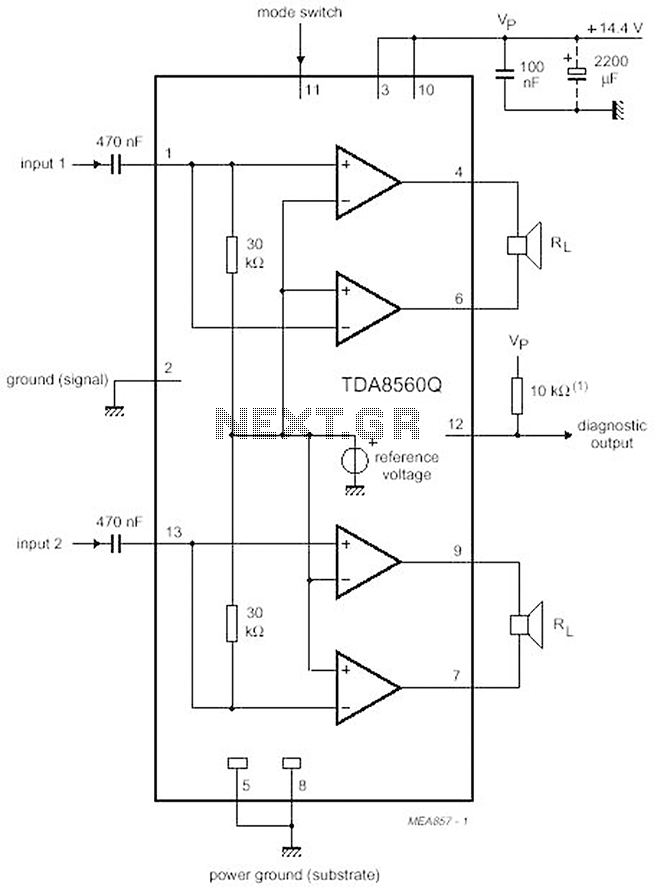
The proposed scheme is straightforward, requiring only a few external electronic components, making it suitable for car audio construction. The output power ranges from 2 to 4 Ohms, providing 2 x 30 W (with a maximum of 2 x...
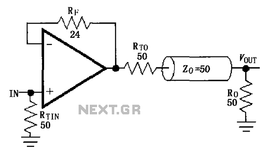
The MAX4450/4451 unity gain line is illustrated in the driving circuit. The MAX4450/4451 features internal compensation, a 24-ohm resistor in series within a feedback loop, along with capacitors and inductors that can reduce the Q value of the feedback...
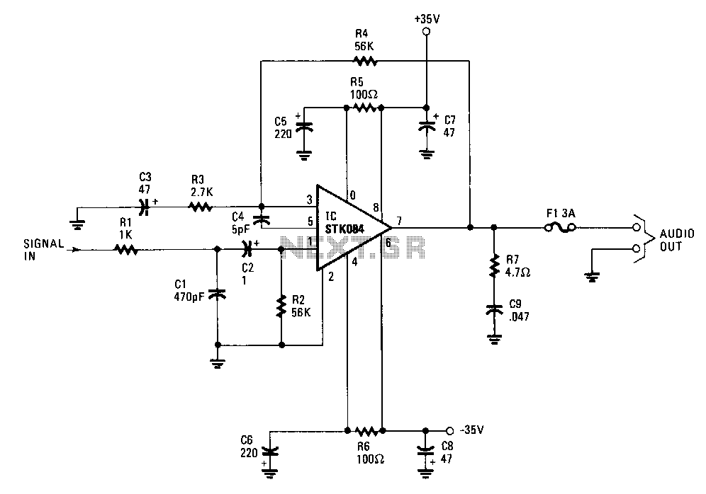
The input is AC coupled to the amplifier through capacitor C2, which blocks any DC signals that may also be present at the input. The combination of resistor Rl and capacitor Cl forms a low-pass filter, effectively eliminating unwanted...
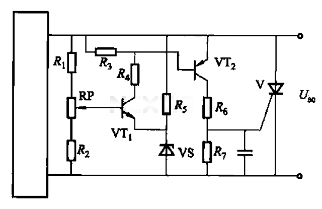
Both circuits are designed solely for overcurrent protection in power supply applications. The circuits in question serve as critical components in safeguarding power supply systems from overcurrent conditions. Overcurrent protection is essential in preventing damage to electrical components and...
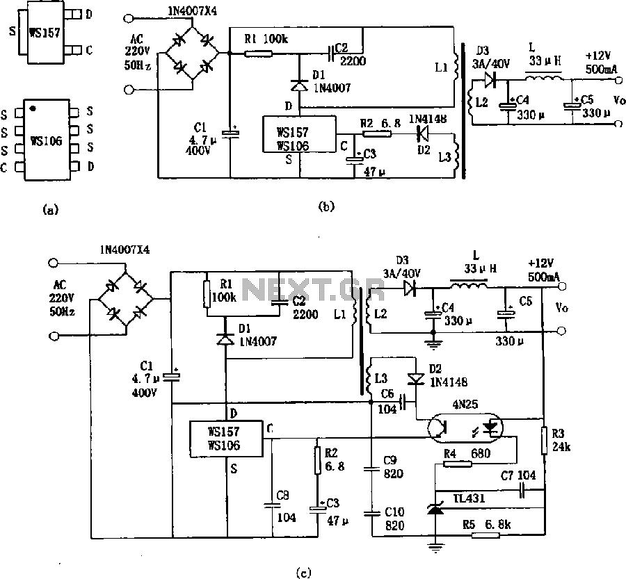
The WS157 or WS106 is a low-power miniature switching power supply that has been developed in recent years. It functions as a regulated switching power supply control device, featuring integrated internal control circuitry and power switches on a single...
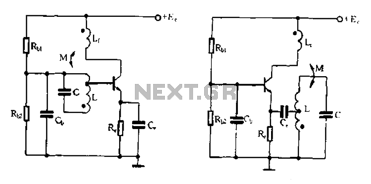
Base frequency selection, frequency-selective emitter type transformer coupled oscillator circuit The described circuit is a transformer-coupled oscillator that utilizes an emitter type configuration to achieve frequency selection. This type of oscillator is designed to generate signals at specific base frequencies,...
Warning: include(partials/cookie-banner.php): Failed to open stream: Permission denied in /var/www/html/nextgr/view-circuit.php on line 713
Warning: include(): Failed opening 'partials/cookie-banner.php' for inclusion (include_path='.:/usr/share/php') in /var/www/html/nextgr/view-circuit.php on line 713