
Simple fourth gear dimmer switch circuit
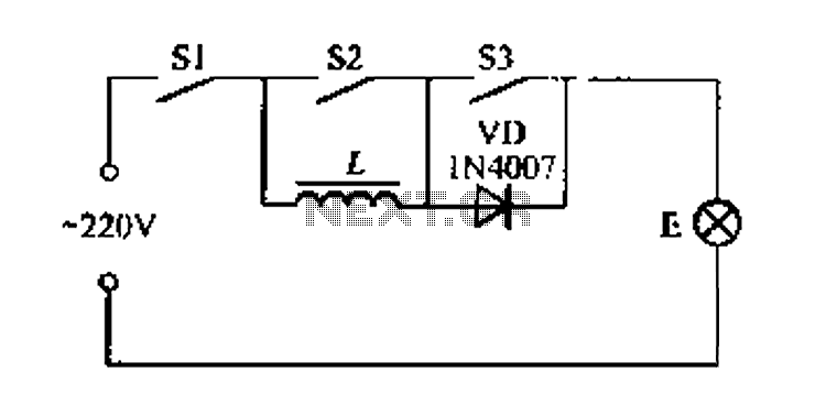
The described circuit utilizes a four-way dimmer switch configuration to control the brightness of a lamp through multiple switch combinations. Each switch (S1, S2, and S3) plays a crucial role in determining the operational state of the lamp. The design allows for various brightness levels, providing flexibility in lighting control based on user preference or ambient conditions.
In its brightest state, all switches are closed, allowing maximum current flow to the lamp. This configuration is ideal for situations requiring full illumination. When switches S1 and S2 are engaged while S3 is disengaged, the lamp achieves a bright state, suitable for general lighting. The intermediate state, where S1 and S2 are closed and S3 is open, offers a clearer light output, which may be preferred for tasks requiring more focused lighting.
The dimmest setting is achieved when all switches are open, effectively turning off the lamp. This feature is particularly useful for conserving energy or when light is not needed. The circuit is designed to operate safely with a 20W electric ballast, ensuring that the lamp functions efficiently without exceeding a total power consumption of 60W. This design consideration is critical for preventing overheating and ensuring the longevity of the components.
Overall, this four dimmer switch circuit provides a versatile and efficient solution for managing lighting in various environments, making it a practical choice for both residential and commercial applications.Easy to take along four dimmer switch circuit shown in Figure 8, which has a 4-speed brightness of combination: When the switch Sl, S2 and S3 compete portion is closed, the lam p E brightest; when Sl, Pa l two together, s2 open lamp E in bright state; when SI, S2 closed, S3 open, light E in a more clear state; stage when Sl, S2, S3 buckle open, light E is the darkest; if S1 is open, light E off. L used 20 - Electric -10W R light ballast sense, E power should not exceed 60W.
Related Circuits

The moisture detector utilizes two transistors and a piezoelectric transducer to emit an alarm tone when water is detected. Transistor Q1 functions as a crystal-controlled oscillator, employing a portion of the piezoelectric transducer XDC, which consists of two piezoelectric...
Create an oscillator circuit using an operational amplifier and a 7.68 MHz crystal. The design should be similar to the schematic provided below, but specifically tailored for a 7.68 MHz crystal. The available components include the crystal, various capacitors,...

The receiver is based on a basic SA612 circuit. The local oscillator (LO) for the 20-meter band operates at approximately 9 MHz, with an intermediate frequency (IF) of 5.068 MHz. The IF filter employs two crystals and has a...
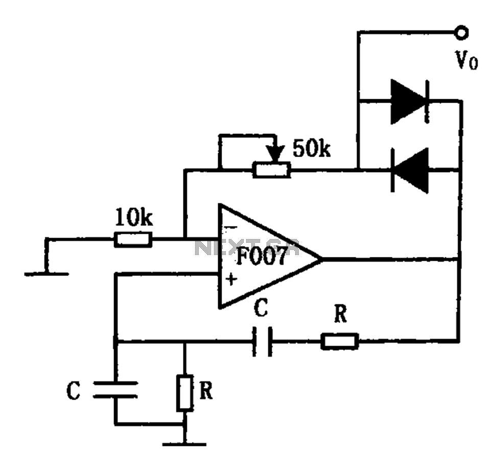
The stable sine wave oscillator circuit is designed to maintain consistent oscillation. The loop gain must be carefully managed; if the gain is excessive, waveform distortion occurs, while insufficient gain can lead to cessation of oscillation. This circuit employs...
This design is for an interpolating scanner, a circuit featuring multiple signal inputs, a control voltage input, and a signal output. The output selectively transitions between inputs, smoothly fading from one to the next as the control voltage increases....

A simple yet reliable car battery tester circuit diagram. This circuit utilizes the popular and easily accessible LM3914 integrated circuit (IC). The LM3914 is straightforward to operate, does not require external voltage regulators due to its built-in voltage regulator,...
Warning: include(partials/cookie-banner.php): Failed to open stream: Permission denied in /var/www/html/nextgr/view-circuit.php on line 713
Warning: include(): Failed opening 'partials/cookie-banner.php' for inclusion (include_path='.:/usr/share/php') in /var/www/html/nextgr/view-circuit.php on line 713