
simple signal injector aids control loop analysis
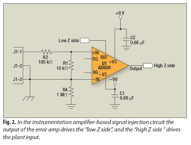
The signal-injection circuit is designed to facilitate control-loop analysis by providing a stable and consistent signal across a frequency range from direct current (DC) to 200 kilohertz (kHz). The circuit's flat frequency response ensures that it can accurately inject signals without introducing distortion or frequency-dependent variations, making it suitable for testing and analyzing control systems.
Isolation from chassis ground is a critical feature of this circuit. This isolation helps to prevent ground loops and other noise issues that can affect the accuracy of measurements. By maintaining a floating ground reference, the circuit can be used in various environments without the risk of interference from external electrical noise.
The circuit can be constructed using a standard instrumentation amplifier, which is readily available in the market. Instrumentation amplifiers are preferred for their high input impedance, low output impedance, and excellent common-mode rejection ratio (CMRR). These characteristics make them ideal for accurately amplifying small signals while rejecting noise and interference.
To build the circuit, the instrumentation amplifier is configured to accept input signals and provide an output that can be injected into the control loop under test. Additional components such as resistors, capacitors, and possibly a power supply may be required to complete the circuit and ensure proper operation. Careful selection of these components will further enhance the performance and reliability of the signal-injection circuit.
Overall, this signal-injection circuit serves as a valuable tool for engineers and technicians involved in control system analysis and testing, allowing for precise signal manipulation and measurement across a critical frequency range.A signal-injection circuit for control-loop analysis is flat from dc to 200 kHz, isolated from chassis ground and easily constructed with a readily available instrumentation amplifier.. 🔗 External reference
Related Circuits
A section of the operational amplifier's output signal is rectified using 1N4148 diodes, followed by filtering, and is then directed to the gate of the FET input shunting circuit. As the output voltage increases, additional input shunting occurs, which...
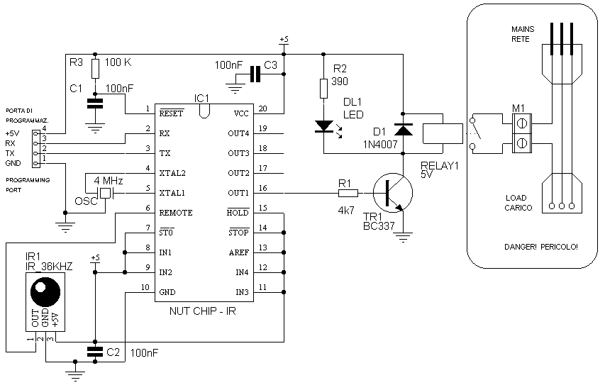
Having to use the infrared remote control, we will procure in addition to modulate the Nutchip infrared receiver. Do not let the name fool you, because more than one module component that looks like a large transistor. We use...
The pitch of the tone is determined by the resistance being tested. The tester can respond to resistances in the hundreds of kilohms range, while also being capable of distinguishing differences as small as tens of ohms in low-resistance...
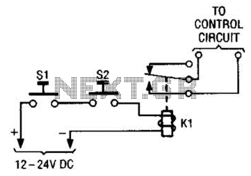
The simple two-hand safety control switch consists of two pushbutton switches connected in series; both must be depressed to energize the relay. The two-hand safety control switch is designed to enhance safety in applications where the operation of machinery or...
The SOS Alarm centralized control circuit is designed for use in calling a hospital bed and can also serve as an anti-theft alarm in multi-storey buildings, dormitories, warehouses, and similar locations. The circuit, as depicted in Figure 13-64, features...
A simple water level sensor or liquid level detector for measuring or detecting a required level of water, liquid, or fluid in a tank, pool, well, aquarium, washing machine, etc. The water level sensor is an essential device utilized for...
Warning: include(partials/cookie-banner.php): Failed to open stream: Permission denied in /var/www/html/nextgr/view-circuit.php on line 713
Warning: include(): Failed opening 'partials/cookie-banner.php' for inclusion (include_path='.:/usr/share/php') in /var/www/html/nextgr/view-circuit.php on line 713