
Simple Safety Circuit Circuit
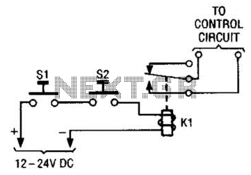
The two-hand safety control switch is designed to enhance safety in applications where the operation of machinery or equipment could pose a risk to the operator. By requiring both pushbutton switches to be activated simultaneously, the system ensures that the operator maintains a safe distance from the moving parts or hazardous areas.
In this configuration, each pushbutton switch is connected in series, meaning that the circuit is only completed when both switches are pressed. The switches are typically momentary contact types, which means they return to their default position when released. This design prevents accidental activation of the relay and ensures that the machinery remains in a safe state when the operator's hands are not in the correct position.
The relay, which is energized when both switches are pressed, can control larger loads or more complex machinery, acting as an interface between the low-power control circuit and the high-power operational circuit. It is essential to select a relay that is rated for the load it will control, ensuring reliability and safety in operation.
In addition, it is advisable to implement additional safety measures such as emergency stop buttons and visual indicators to further enhance the safety of the system. Proper labeling and training for operators are also critical to ensure that the two-hand control mechanism is used correctly, thereby minimizing the risk of accidents. The simple two-hand safety-control switch shown here is little more than two pushbutton switches connected in series; both must be depressed in order to energize the relay. 🔗 External reference
Related Circuits
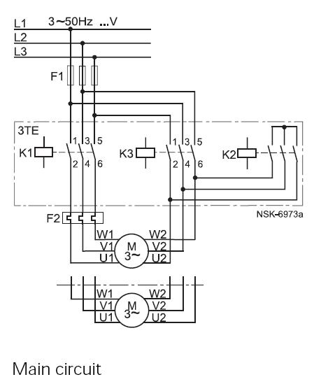
This method reduces starting current and starting torque. The device typically consists of three contactors, an overload relay, and a timer for setting the duration in the star position (starting position). The motor must be delta connected during normal...

A Field Effect Transistor (FET) is an amplifying device where the output current is influenced by the input voltage. The FET preamplifier described here is sensitive. The Field Effect Transistor (FET) operates by utilizing an electric field to control the...
The following circuit illustrates an Automatic Room Power Control Circuit Diagram. This circuit is based on the NE555 integrated circuit (IC). Features include the use of two Light Dependent Resistors (LDRs). The Automatic Room Power Control Circuit utilizes an NE555...

The interface circuit is placed between the computer's standard video signal output terminal and the television. It amplifies the standard 1V (Peak-to-Peak) video signal to 3V (Peak-to-Peak). The negative feedback circuit consists of transistors T1 and T2, providing a...
The circuit utilizes a 555 timer along with resistors R4, R5, and capacitor C1 configured in a controllable multivibrator mode. This setup forces the reset terminal (pin 4) to a specific state, allowing for control of the external logic...
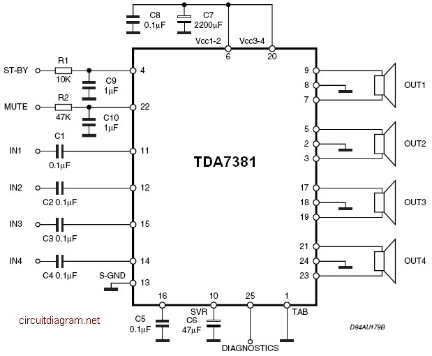
The amplifier is a quad amplifier circuit (amplifier with four inputs and four outputs) based on the TDA7381. This amplifier is designed for car audio systems, but it can also be utilized for other applications. The circuit has a...