
simple Sound Trigger
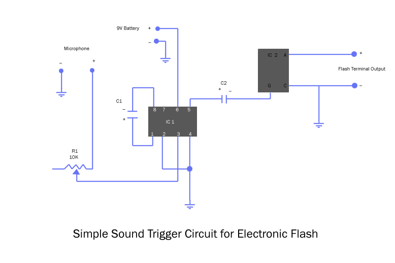
The described circuit utilizes an LM386N amplifier IC, which is a low-voltage audio power amplifier. It is configured to amplify the weak audio signals from the microphone, which typically produces a low-voltage output. The gain of the amplifier is set at 200 due to the use of capacitor C1, ensuring that even faint sounds can trigger the SCR. The SCR serves as an electronic switch that controls the high-current flash circuit, allowing for a safe and efficient method of triggering the flash without direct electrical contact.
The variable resistor (potentiometer) is crucial for adjusting the sensitivity of the microphone input, allowing the user to tailor the circuit's response to different sound levels. This feature is particularly useful in environments with varying background noise, ensuring that the flash only fires in response to intended sounds.
When assembling the circuit, it is essential to follow the schematic closely, ensuring that all connections are secure and correctly placed on the breadboard. The use of hard wires and connectors enhances the robustness of the project, making it suitable for repeated use and experimentation.
In practical applications, the flash can be used for photography to capture high-speed events that are otherwise difficult to photograph due to the limitations of camera shutter speeds. The described setup offers an engaging way to explore the interaction between sound and light, providing a platform for further experimentation with different sound sources and flash settings.Basically, the microphone inputs go to ground (-) and to the middle terminal of the 10K variable resistor (potentiometer) - this variable resistor is your sensitivity control. The output from the potentiometer goes to pin 3 of the amplifier IC, and the output of the amplifier goes through a capacitor to the "gate" terminal of the SCR (silicon-controlled rectifier - basically a switch).
The SCR has three pins: gate, anode and cathode. You hook your flash up to the anode (+ flash wire) and the cathode (- flash wire, which also goes to ground in the circuit). When a sound is picked up by the microphone and amplified by the amplifier, if it`s loud enough to go over 2 volts on the output of the amp, it opens the "gate" on the SCR and allows current to flow between the two flash wires, shorting them and firing the flash.
Capacitor C1 sets the gain of the amplifier IC to 200, so it amplifies the tiny voltage from the microphone 200 times. It`s not that tough, there are only 8 wires to connect, plus 1 potentiometer and 2 capacitors. I soldered hard breadboard wires to the leads of the microphone and PC cord to make them easier to plug into the breadboard and more sturdy - you could also use jacks (which I probably will, as I`m going to build this so it`s a bit more robust on a real circuit board).
Just follow the connections in the circuit diagram, hooking things up where they`re supposed to go. On a breadboard like this, the verticalcolumns on each side of the middle divider are all connected, so any wire or IC pin put in that column is connected to anything else in the same column. Look at the furthest pin to the right on the little square IC (that`s the LM386N amplifier) - there`s a blue wire going from that to the ground bus on the breadboard.
If you`ve ever built a circuit before, this should take you 10 minutes. If you`ve never done one, maybe an hour. Once the circuit`s finished, hook a 9V battery (not shown in the picture, the two leads at the top left go to the battery) to it to power it. Then attach your flash to the PC cord, and turn the flash on. Set the mic somewhere, and snap your fingers or clap your hands in front of it - the flash should fire.
If it`s too sensitive or not sensitive enough, turn the wheel on the variable resistor to adjust the sensitivity. That`s it! This circuit has no "delay" function, but you can control the delay between the actual event and the flash firing by moving the mic - the closer it is to the thing making the sound, the shorter the delay.
and the further it is, the longer the delay. Little changes can make a big difference, so only move it an inch or so at a time. Ideally, set up your shot so the "event" makes a sharp noise (light bulb popping, balloon popping, glass smashing, etc. ). Focus and compose with the lights on, then put your camera on "B" (bulb), turn off the lights so it`s VERY dark, open the shutter and lock it open.
Start the event, and the flash will trigger on the sound cue. Close the shutter, then turn the lights back on. then check your shot! Incidentally, this trigger will also fire the camera shutters on SLRs that have a simple switch remote shutter release - there`s no current in the outputs, the SCR makes basically a simple closed switch. Lots of fun things to try. I`ll do a follow-up on flash settings, lighting, etc. a little later. 🔗 External reference
Related Circuits
This simple cable tester can be used to check two-wire cables such as coaxial cables, telephone cables, audio cables, and others. The circuit is powered by a 9V battery. To operate, plug in the cable and press the "TEST"...
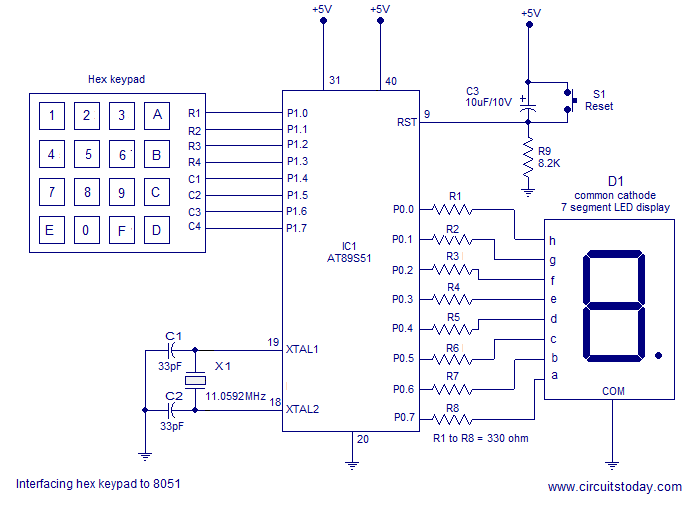
Interfacing a hex keypad to an 8051 microcontroller. The AT89S51 is utilized in this setup. A circuit diagram and assembly language program are included. A testing video is also provided. The interfacing of a hex keypad with the AT89S51 microcontroller...

This is a circuit diagram designed for high voltage DC impedance. It utilizes the uA741 integrated circuit (IC), which functions as a non-inverting DC amplifier. The circuit incorporates negative feedback through DC meters to achieve a full-scale deflection of...
The circuit is fundamentally based on a well-tested simple microphone preamplifier design. A prototype of this circuit has been constructed and has demonstrated effective performance. The Sound Blaster soundcard series (SB16, SB32, AWE32, and AWE64) features a microphone input...
There are many who built the Easy Programmer or C-52 Evaluation Board, asking for the RS232C level converter chip, DS275. Many have changed to MAX232 instead, because it is not available in their home. Here is another simple and...
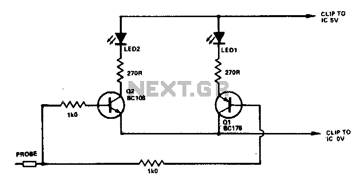
If the probe is connected to logic 0, Q1 will be activated, illuminating D1. When connected to logic 1, Q2 will be activated, illuminating D2. Any NPN or PNP transistors can be used for Q1 and Q2. Likewise, D1...