
Simple DIY Cable Continuity Tester
The cable tester circuit is designed for versatility, accommodating a variety of two-wire cables while providing clear feedback on the cable's status. The operation begins with the application of power from a 9V battery, which is essential for the functionality of the op-amps and indicator LEDs. The dummy resistor, with its specified resistance, plays a crucial role in determining the state of the cable under test.
The voltage divider configuration is central to the testing process. It utilizes the principles of Ohm's law and voltage division to assess the condition of the cable. When a short circuit occurs, the voltage drop across the dummy resistor is significantly reduced, leading to a voltage reading that triggers the lower comparator. Conversely, an open circuit results in a maximum voltage reading, activating the upper comparator. These conditions are visually represented by the corresponding LEDs, providing immediate feedback to the user.
The choice of op-amp, such as the JRC4558, is based on its availability and performance characteristics. This component is capable of handling the necessary signals and can be substituted with other op-amps if required. The additional battery check circuit enhances the functionality of the tester, ensuring that users are aware of the battery condition before conducting tests, thereby preventing false readings due to insufficient power.
Incorporating a buzzer into the design adds an auditory signal to the visual feedback of the LEDs, making the tester more user-friendly, especially in environments where visual indicators may be less noticeable. The design allows for customization, enabling users to modify the circuit according to their specific needs and preferences. Overall, this cable tester circuit provides a reliable and efficient means of diagnosing cable issues, making it an essential tool for technicians and hobbyists alike.This simple cable tester can be used to check 2 wire cable such as coax cable, telephone cable, audio cable and etc. Power the circuit using 9V battery. Plug in the cable and push "TEST" button. The dummy resistor is connected to the end of the cable which has 75ohm resistor inside. The tester will show only 3 conditions, "SHORT", "OPEN" and "GOOD ". The method is to check resistance of the dummy resistor at the "Terminator". The idea is simple. Imagine there is a short circuit cable under testing. The wire will act as nearly zero ohm resistor thus making the voltage divider near the dummy resistor to divide the 9V into 4. 5V. Calculate it your self [ ( 1k / ( 1k + 1k ) ) * 9V = 4. 5V ]. 4. 5V is below than the lower "Comparator" limit (Vref 4. 57V). It will trigger the lower "Comparator" and make "Short" LED to light up. Now for the open circuit cable. Assuming the open circuit cable has an infinite ohm. Voltage divider near the dummy resistor will give 9V. This is more than the upper "Comparator" limit (VRef 4. 8V) and will trigger make "Open" LED light up. Other than that (both lower and upper "Comparator" didn`t trigger) the "GOOD" LED will light up. For the op-amp, I`m using JRC4558 dual op-amp since I have it in my stock. You may use 741 op-amp or other multi-purpose op-amp. The extra circuit supplied is to check the battery condition. Low battery voltage (below than ~6. 9V) will show "RED" light up. Else will show "GREEN" LED light up. The basic, if there is a small amount of current go through the zener (reverse bias), the first transistor (left) will be turned on making the "GREEN" LED turn on.
Other than that the second transistor (right) will be turned on and "RED" LED will light up. You add in buzzer to the circuit to make it give an audible alarm. The best is to alert us whenever the cable under test is not "GOOD". So, adding a resistor, transistor and a buzzer/beeper to the last NAND (near "GOOD" LED) will do the job. Use your own creativity for this. :-). 🔗 External reference
Related Circuits
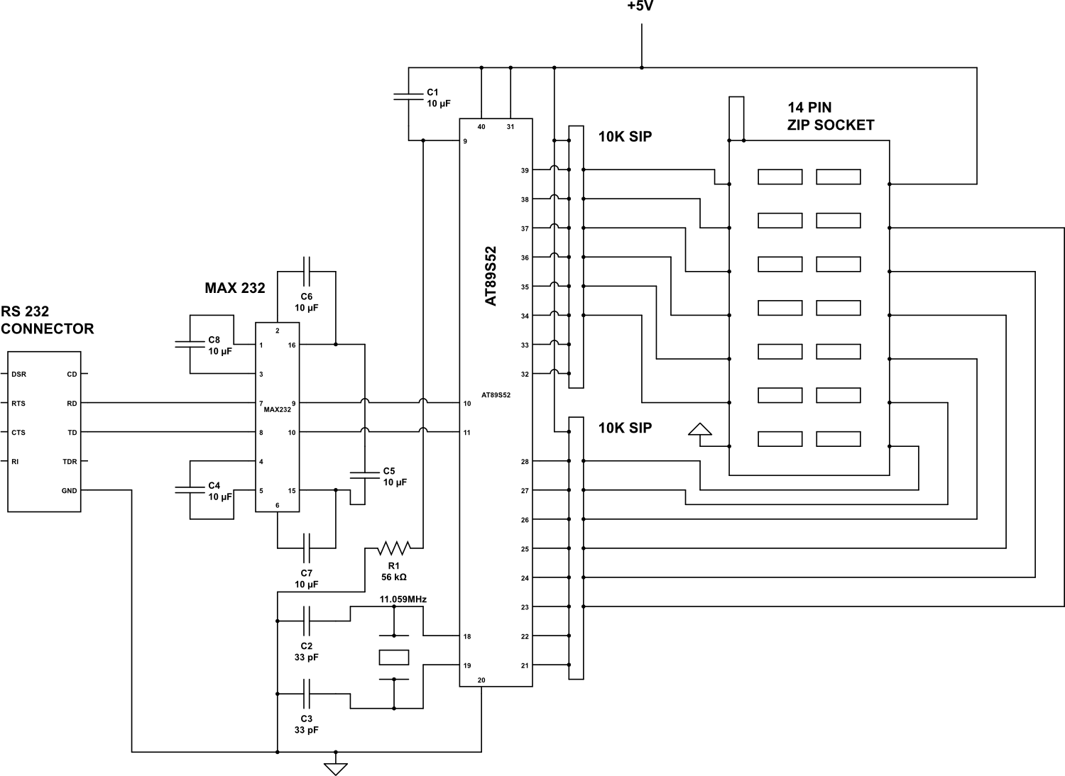
Check the following ICs: 7400, 7402, 7404, 7408, 7432, 7486. A Visual Basic program is utilized to display the results on the PC. The microcontroller AT89S52 receives the IC number from the PC, verifies the logic gates with the...
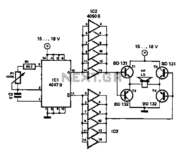
A low-cost and straightforward repellent circuit can be utilized for deterring rats, mice, and other animals, as illustrated in the electronic figure below. The circuit employs a CMOS integrated circuit of type 4047, which functions as a relaxation oscillator....
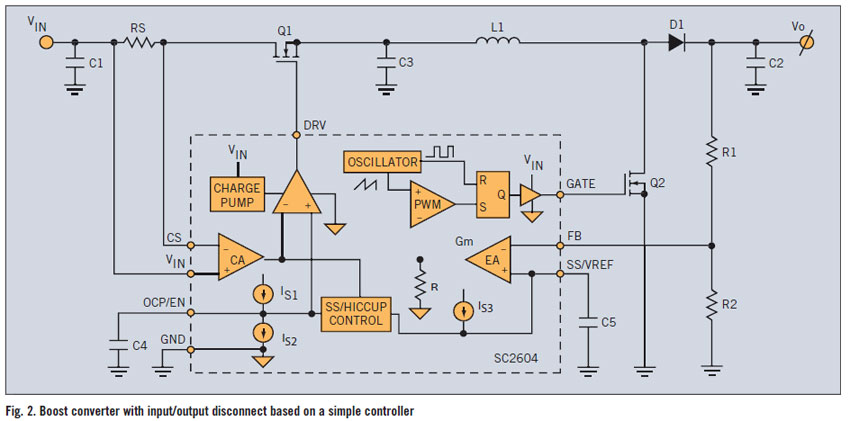
A PWM boost converter in a simple controller has a DC path from input VIN to VOUT, which is utilized for high-efficiency power conversion. A PWM (Pulse Width Modulation) boost converter is an essential component in power electronics, designed to...
The circuit presented generates a smooth, piercing, wailing siren with minimal components. Additionally, three spare gates of the hex inverter IC1 are available, allowing the possibility of creating a cacophony by operating two sirens from the same integrated circuit....
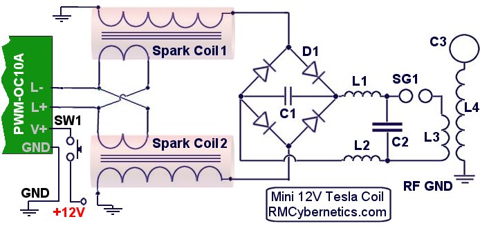
The DIY Plasma Gun is a compact, homemade Tesla Coil gun powered by an 18V battery. It features a specialized plasma discharge terminal capable of emitting ionized gas and flames. The entire system is housed within the casing of...

With this simple measuring device can: Determine the Zener voltage up to 25V. The connections of cathode and anode of each diode finding. Check if a diode fails. Silicon, germanium and Schottky diodes distinguish. LED test and the V...