
Simple logic probe
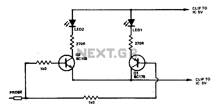
The circuit described operates as a simple logic level indicator using two transistors and two light-emitting diodes (LEDs). The configuration allows for the visual representation of digital logic states—logic 0 and logic 1—through the illumination of the respective LEDs.
In this circuit, Q1 and Q2 serve as switching elements. When the probe detects a logic 0 (typically represented by a low voltage, close to 0V), Q1 is turned on. This activation allows current to flow through LED D1, causing it to light up. The choice of using an NPN or PNP transistor for Q1 depends on the desired circuit configuration, such as common emitter or common collector setups.
Conversely, when the probe detects a logic 1 (a higher voltage, typically around the supply voltage), Q2 is activated. This allows current to flow through LED D2, illuminating it. Again, either an NPN or PNP transistor can be utilized for Q2, based on the overall design requirements.
D1 and D2 can be selected from a wide range of LEDs, based on color, brightness, and forward voltage specifications. It is important to ensure that the current passing through the LEDs is limited to safe levels, which can be achieved by incorporating current-limiting resistors in series with each LED. The resistor values can be calculated using Ohm's Law, considering the forward voltage drop of the LEDs and the supply voltage.
This circuit can be employed in various applications, such as simple logic testers, educational projects for understanding digital logic, or as visual indicators in more complex electronic systems. The simplicity and versatility of the design make it an effective tool for demonstrating the relationship between digital signals and visual output.If the probe is connected to logic 0, Ql will be turned on lighting Dl. At logic 1, Q2 will be turned on lighting D2. For Ql and Q2 any NPN or PNP transistors will do Similarly, Dl and D2 can be any LEDs. 🔗 External reference
Related Circuits
This code lock circuit is an electronic combination lock designed for daily use. It only responds to the correct sequence of four digits entered remotely. If an incorrect key is pressed, the lock resets. The lock code can be...
This circuit utilizes the widely available LM3914 integrated circuit (IC). The IC is straightforward to operate, does not require external voltage regulators due to its built-in voltage regulation feature, and can be powered from nearly any voltage source. The LM3914...
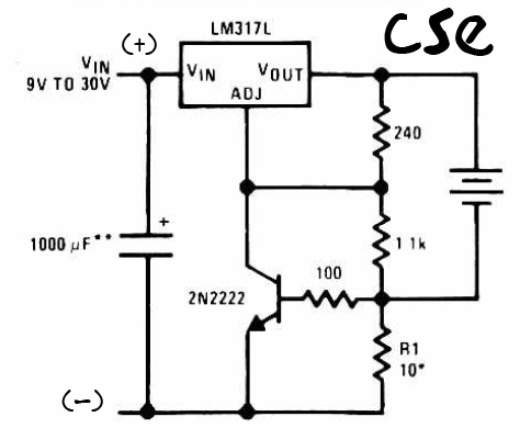
This is a straightforward charger designed for 9V to 30V batteries, primarily operated by the IC LM317L and a 2N222 transistor. It utilizes direct input DC voltage, and a recommended capacitor of 1000µF is included for filtering the output...
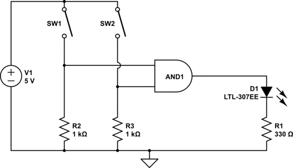
The AND output will be high when both switches are closed. However, there is no assurance regarding the input levels when the switches are open, resulting in unpredictable outcomes. In an electronic circuit utilizing an AND gate, the operation is...
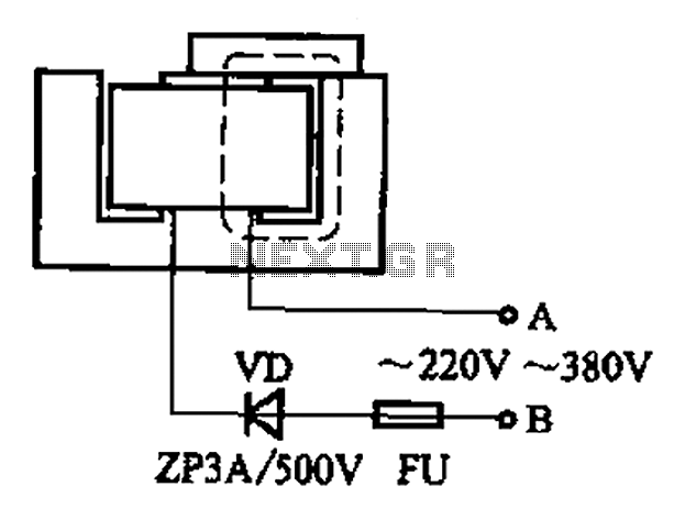
After some minor loss of field magnets, they can be re-magnetized using a homemade method. A scrap of exchanges and contacts, as well as other models like CJ10-60 ~ 15, can be utilized. The circuit operates at 0A (compatible...
This tester can be used to check the polarity of any power source, and is therefore very useful when installing automotive equipment, alarm systems or anything else you can think of. Because this circuit is so simple and cheap,...