
Square Wave Oscillator using Comparator/Op-Amp
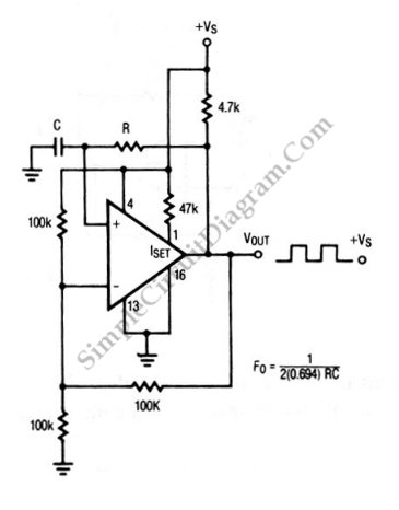
The square-wave oscillator circuit utilizes the LP165/365 comparator to generate a continuous square wave output. The operation of this circuit relies on the feedback mechanism that establishes a stable oscillation frequency. The comparator serves as the central element, comparing two input voltages: a reference voltage and the voltage derived from the output through a resistor-capacitor (RC) network.
In typical configurations, the circuit includes a resistor (R) and capacitor (C) connected in series, which determines the timing characteristics of the oscillation. The charging and discharging of the capacitor through the resistor create a time delay that influences the frequency of the output waveform. The output of the comparator toggles between high and low states as the voltage across the capacitor reaches the threshold levels set by the reference voltage.
The frequency of oscillation can be calculated using the formula \( f = \frac{1}{T} \), where \( T \) is the time period of one complete cycle. The time period is influenced by the values of the resistor and capacitor, and it can be adjusted to achieve the desired frequency. The output waveform is typically a symmetrical square wave, characterized by equal high and low durations.
For practical applications, additional components such as diodes or additional comparators may be incorporated to shape the waveform or enhance stability. The design may also include provisions for power supply decoupling to ensure reliable operation in various environments. Overall, the square-wave oscillator circuit based on the LP165/365 comparator is a versatile and widely used configuration in various electronic applications, including clock generation, signal modulation, and waveform generation.The circuit shown in this schematic diagram is a square-wave oscillator circuit. The main component of this oscillator circuit is LP165/365 comparator. As.. 🔗 External reference
Related Circuits
This is a circuit schematic diagram for VU meters. The circuit is controlled by the IC TL072 and follows a measurement circuit as per the National general application. The input circuit around IC1 is designed for adaptation and amplification...
This amplifier is designed for outdoor installation and is connected to an indoor power line box. It utilizes either 50-ohm or 75-ohm coaxial cables for the connection between indoor and outdoor units. The amplifier circuit board is depicted in...
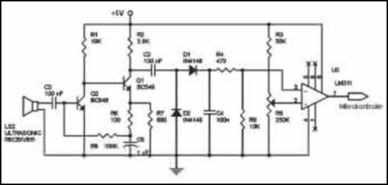
Ultrasonic receivers detect an ultrasonic signal emitted by an ultrasonic transmitter at a specific frequency. The received signal is filtered using a band-pass filter circuit that allows only the predetermined frequency range to pass. The output signal is then...
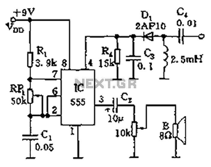
The circuit features a 555 timer integrated circuit along with components R1, RP1, C1, and others, which together form an audio oscillator. The frequency of the oscillator is determined by the formula f = 1.44 / ((R1 + 2...
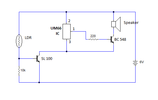
This article provides instructions for creating a light-sensitive morning alarm circuit. The circuit utilizes an LDR (Light Dependent Resistor) or photoresistor to detect morning light, which triggers the alarm section. When light is detected, the circuit produces a melodious...
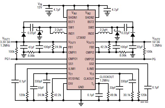
The LT3692 dual current mode PWM step-down DC-DC converter circuit, featuring two internal 3.5A switches, can be designed into a simple power supply circuit suitable for various electronic applications, such as distributed supply regulation or automotive circuits. The LT3692...
Warning: include(partials/cookie-banner.php): Failed to open stream: Permission denied in /var/www/html/nextgr/view-circuit.php on line 713
Warning: include(): Failed opening 'partials/cookie-banner.php' for inclusion (include_path='.:/usr/share/php') in /var/www/html/nextgr/view-circuit.php on line 713