
Simple Surround Sound Decoder
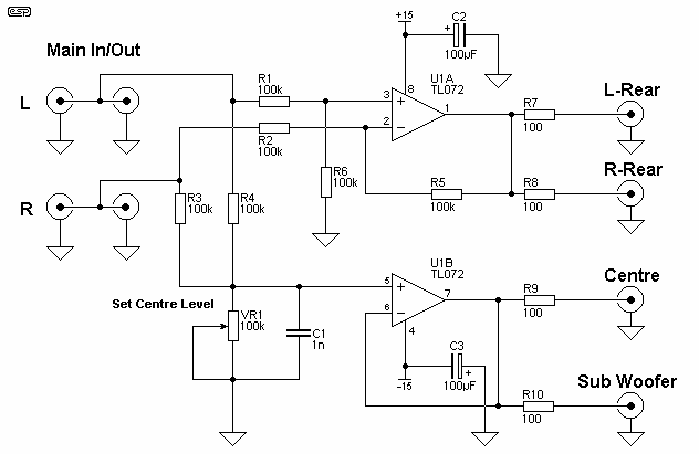
The described surround-sound decoder utilizes the Hafler principle, which effectively creates a pseudo-surround sound experience by deriving a rear channel signal from the difference between the left and right audio channels. In a typical stereo setup, the decoder processes the incoming stereo signals to generate an output that can drive additional speakers placed behind the listener, thereby enhancing the spatial audio experience.
The circuit typically involves a differential amplifier configuration that takes the left and right channel inputs and computes their difference. This difference signal is then amplified to drive the rear speakers. The output stage of the decoder must be carefully designed to ensure that it can handle the varying power demands of the rear speakers, particularly in setups where the main speakers are bi-amped or bridged.
In cases where the main speakers are bi-amped, the absence of a full-range signal can lead to inadequate power for the rear speakers, as the decoder relies on the difference signal, which may not be sufficient in such configurations. Additionally, the decoder lacks a level control mechanism, resulting in a fixed output level that may not match the desired volume for the rear speakers.
To address these limitations, an adjustable gain stage could be integrated into the circuit to allow for fine-tuning of the rear speaker output. This could be achieved with a variable resistor or potentiometer that adjusts the gain of the difference signal before it reaches the rear speaker outputs. Furthermore, to ensure compatibility with mono signals, a summing amplifier could be included to combine the left and right channel signals, producing a suitable output for the rear speakers even when the input is not stereo.
In summary, while the Hafler surround-sound decoder provides a straightforward solution for creating a surround sound experience, careful consideration must be given to its design, particularly in systems with bi-amped or bridged main speakers, to ensure optimal performance and control over the rear channel output.This surround-sound decoder is based on the "Hafler" principle, first discovered by David Hafler sometime in the early 1970s. The original idea was to connect a pair of speakers as shown in Figure 1, for use as the rear speakers in the surround setup.
This is ok just as it stands, but problems are created if the main speakers are bi-amped or using bridging, for example, since there is no longer a full-range / full power signal available for the rear speakers. There is also no way to control the level reproduced, since it will always simply be the difference signal between left and right channels.
If the signal is mono, then the signal in both channels will always be more or less identical, and there will be no output from the rear speakers at all. 🔗 External reference
Related Circuits
This circuit provides a straightforward method for measuring the voltage of a low-impedance voltage source. It operates as follows: P1, a 1-W potentiometer, acts as a voltage divider in conjunction with resistor R1. The voltage at their junction is...
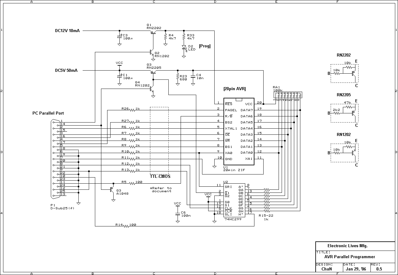
These are simple AVR programmers. I designed and built four different programmers for various environments: LPT controlled parallel programmer, LPT controlled ISP adapter, COM controlled ISP adapter, and COM controlled generic SPI bridge. Additionally, COM controlled adapters can be...
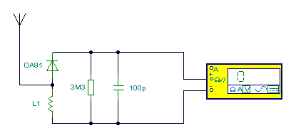
The multimeter should be set to the lowest DC volts range for maximum sensitivity, typically 200mV DC for most meters. The circuit operates effectively at VHF frequencies, approximately 100MHz, yielding satisfactory results. The inductor L1 consists of 7 turns...
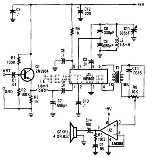
Using an NE602 heterodyne detector and U1 as an RF amplifier, this receiver tunes the middle portion of the low-frequency spectrum from 150 to 250 kHz. U2 is a loudspeaker amplifier. The described circuit employs an NE602 integrated circuit...

Creating a variable space in a small room can be enjoyable; however, designing an actuator to move a wall or room partition poses challenges. This can be achieved using an analog audio line delay. To implement a system that allows...
This simple circuit illustrated in the schematic diagram activates the switch using sound. It can be utilized for various applications, such as automatic (sound-controlled) disco lights or car LED light shows. The transistor Q1 amplifies the audio from the...
Warning: include(partials/cookie-banner.php): Failed to open stream: Permission denied in /var/www/html/nextgr/view-circuit.php on line 713
Warning: include(): Failed opening 'partials/cookie-banner.php' for inclusion (include_path='.:/usr/share/php') in /var/www/html/nextgr/view-circuit.php on line 713