
Sound-Activated Lamp circuit diagram (Relay/Switch)
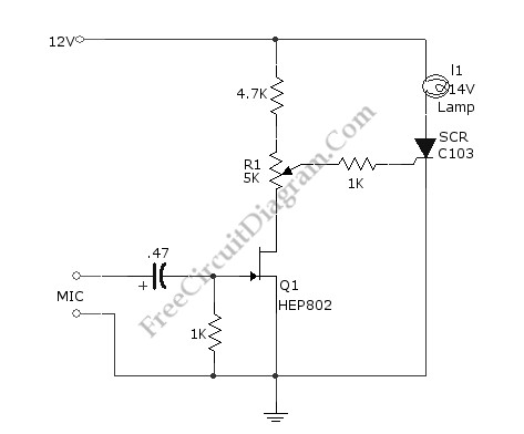
The circuit operates by detecting sound levels through a microphone, which converts sound waves into an electrical signal. The microphone's output is typically a low-level audio signal, which is insufficient to drive most electronic components directly. Therefore, Q1, a transistor, is employed as an amplifier to boost this signal.
When sound is detected, the microphone generates a corresponding electrical signal that is fed into the base of the transistor Q1. The transistor is configured in a common-emitter configuration, which provides significant voltage gain. The amplified output from the collector of Q1 can then be used to drive a relay or another switching device, allowing for control of larger loads such as lights or sound systems.
The resistor R1 plays a critical role in setting the threshold for activation. By adjusting R1, the user can fine-tune the circuit's sensitivity to sound, ensuring that it only activates in response to desired sound levels. If the signal at the base of Q1 exceeds approximately 0.7 volts, the transistor will enter saturation, allowing current to flow from the collector to the emitter, thus activating the connected load.
Additional components may be included in the circuit for enhanced functionality. For instance, a capacitor could be added in parallel with R1 to filter out high-frequency noise, ensuring that only significant sound events trigger the circuit. A diode might also be incorporated to protect the circuit from back EMF generated when using inductive loads like relays.
This sound-activated switch circuit is versatile and can be adapted for various applications, including sound-activated decorations, automatic lighting systems, and interactive displays, making it a useful tool in both hobbyist and professional electronic projects.This simple circuit shown int the schematic diagram actives the switch using sound. We can use this circuit for various applications, such as automatic (sound-controlled) disco light or car s LED light show. The Q1 amplify the audio from mic. The R1 is used to adjust the peak of signal to greater than about 0.7 volts, act as sensitivity adjuster.
A certain l.. 🔗 External reference
Related Circuits

This is an FM wireless transmitter circuit designed to operate a microphone without the need for a cable connecting the microphone to the amplifier. The FM wireless transmitter circuit typically consists of several key components: a microphone, an oscillator, a...
Working with lasers can be enjoyable and intriguing, but it can also be costly. High voltage power supplies for laser tubes are often more expensive than the tubes themselves. However, this power supply can be constructed using common components...
The circuit employs an infrared (IR) phototransistor, designated as Q1, to sense the IR output signal from a remote control. The output from Q1 is then amplified by a PNP transistor, labeled Q2, which activates LED1. This illumination indicates...
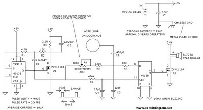
This is a door knob touch alarm designed for home security purposes. The alarm will activate when someone touches the metal door knob. This circuit will not function on a fully metal door. Currently, circular batteries are used, but...

This timer circuit is designed to turn off a specific device after approximately 35 minutes. It can be utilized to switch off appliances such as radios, TVs, fans, and pumps after a predetermined duration of 35 minutes, contributing to...
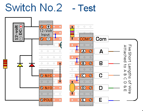
The prototype of Keypad Switch No. 2 was constructed using only the stripboard layout as a reference. If the layout has been accurately reproduced, a functional circuit will result. Once the layout is confirmed to be correct and a...