
simple swr and pwr meter

In the realm of RF (Radio Frequency) engineering, SWR and power meters are essential tools for assessing the efficiency of antenna systems and ensuring optimal performance. The operation of these meters is based on the principles of transmission line theory, where the relationship between forward and reflected power is critical. The directional coupler in instruments like the Bird Series meter functions by splitting the input signal and directing it through two paths, allowing for the measurement of both forward and reflected power without interference.
The calibration of these meters is crucial, as it directly affects measurement accuracy. The meters are designed to work with specific impedance values, typically 50 ohms, which is standard in many RF applications. When the load impedance deviates from this value, the reflected power readings may not accurately reflect the actual performance of the system. Therefore, users must ensure that their measurement environment matches the calibration settings of the meter.
Bridge circuits used in some SWR meters serve a similar purpose, allowing for more versatile applications, especially in HF bands. These circuits utilize the principle of impedance matching to provide accurate power measurements across varying frequencies and load conditions. The rectification process converts the AC voltage to a DC signal, which is then displayed on the meter. This conversion is essential for providing a stable reading that corresponds to the power levels being measured.
Furthermore, the small RC time constant in the measurement circuits is a design consideration that limits the response time of the meter. This characteristic, while beneficial for measuring steady-state power levels, poses challenges for capturing transient signals, such as those found in modulated transmissions. As a result, these meters are better suited for continuous wave signals rather than dynamic or pulsed signals.
In conclusion, while SWR and power meters like the Bird Series provide valuable insights into RF performance, users must be aware of their limitations, particularly regarding PEP and average power measurements. Understanding the fundamental principles behind these instruments, including calibration, impedance matching, and rectification processes, is crucial for accurate power measurement in amateur radio applications.Many SWR / Power meter used by amateurs to the extent reasonably accurate continuous average power with a CW key-down signal, but can not reliably be used with other (modulated) signals PEP or average power measurement. These laws seek to show why the power measurement can be a sensitive issue, and because the interpretation of a yardstick of power
can be a lot of attention and knowledge of construction and the characteristics of the instrument. A reflectometer-type SWR meter can be calibrated to give power back and forth (PF, Pr) on a power supply. A classic example is the 1943 Bird Series power meter, which is a directional coupler is used to obtain a sample voltage proportional to the voltage wave or forward or backward on the feeder (VF, VR).
Other systems, perhaps more suitable for HF, then use a bridge circuit to perform the same function. The sample voltage is then rectified and displayed on a meter that is calibrated in watts. If the counter is typically a coil, the scale, so the numbers on the scale, representing the power, are proportional to the square of the applied voltage or the current calibration. The theory of this type is very simple and is based on the concept represented by PF = Vf2/Zo. Note that if the power supply has an impedance that differs from the value of how the instrument is calibrated, there will be a mistake.
The output voltage of the rectifier is a solid phase of VF or VR, and this is expected in the calibration of the meter. Examples of directional coupling, and bridge-type reflectometers are shown in Figures 1 and 2, while the bird directional coupler means 43 is illustrated in Figure 3.
Note that in all cases the measurement circuit, a combination with a small RC time constant, making the system unsuitable for the measurement of PEP, and the absence of a specific device quadratic, making them unsuitable for measuring the average power. 🔗 External reference
Related Circuits
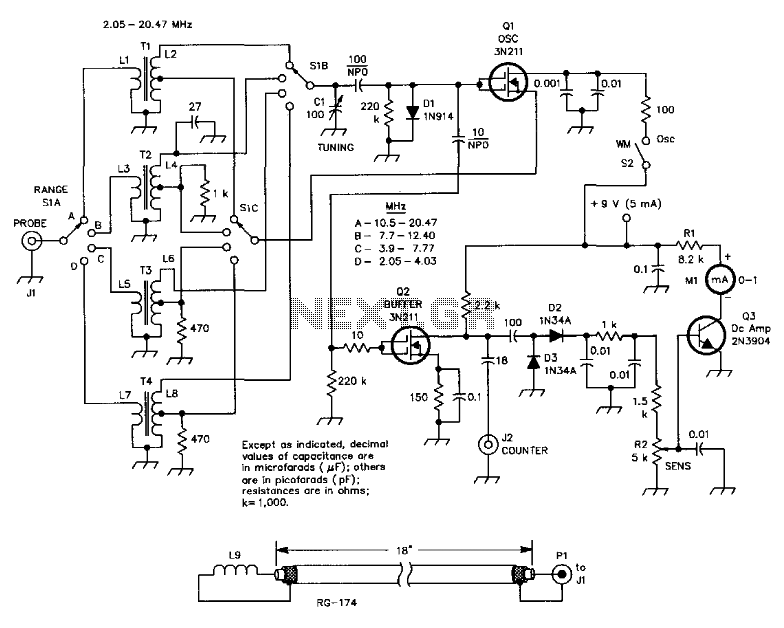
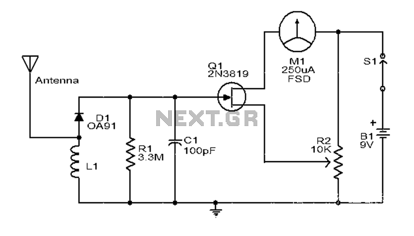
This circuit is designed for checking resonances in tuned circuits, antennas, and similar applications, covering a frequency range of 2 to 20 MHz. Q1 acts as an oscillator that can be tuned across this range using capacitor C1 and...
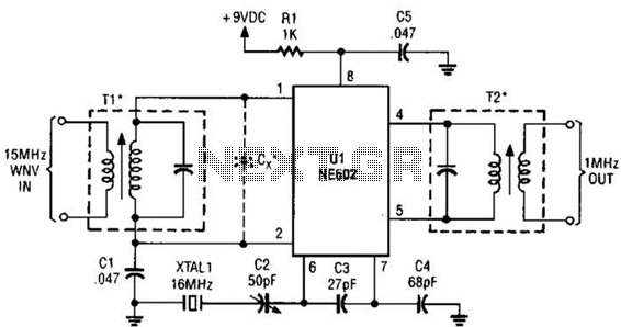
This simple frequency converter mixes the 15-MHz WWV/WVH signal with a 16-MHz signal from the local oscillator (LO) to convert it down to 1 MHz, enabling it to be received on an AM-band receiver. The frequency converter operates by utilizing...
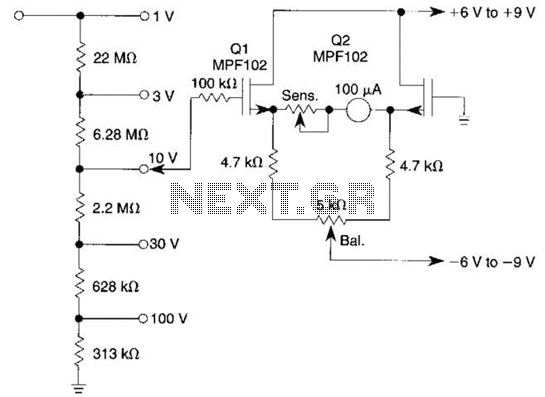
This voltmeter utilizes a pair of JFETs in a balanced-bridge source-follower amplifier circuit. Q1 and Q2 should be matched within 10% for IDSS. This configuration minimizes meter drift and maintains bridge balance over temperature. The described voltmeter is an advanced...
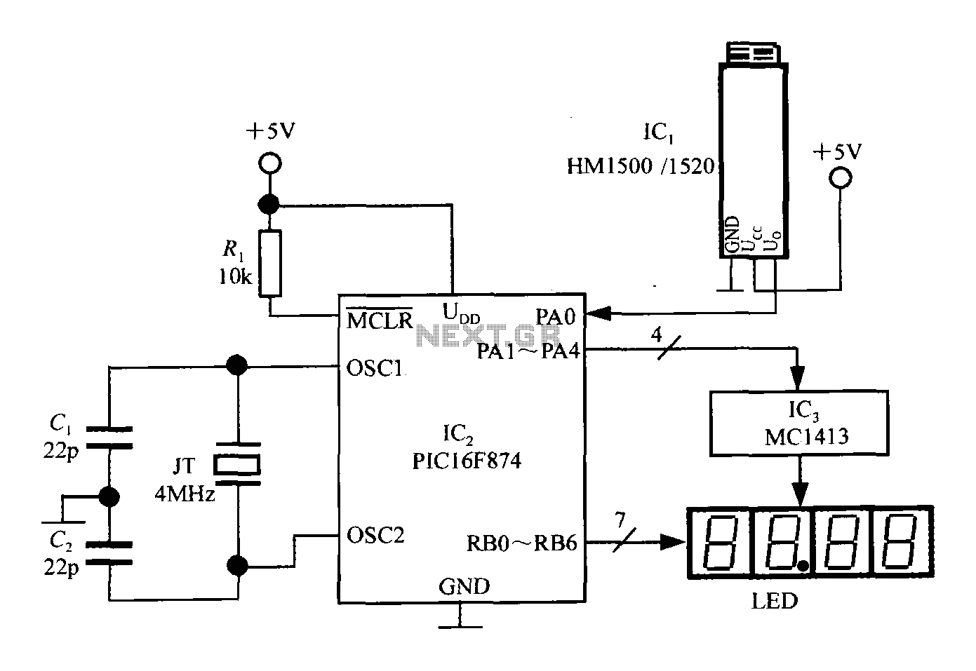
An intelligent humidity meter circuit utilizing the HM1500/1520 humidity sensor and a microcontroller configuration. The circuit operates on a +5V power supply and incorporates four common cathode LED digital displays. It employs three integrated circuits: IC1 is the HM1500/1520...
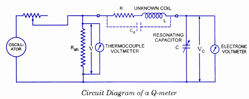
Every inductor coil possesses a certain amount of resistance, and it is essential for the coil to have the lowest possible resistance. The quality factor, or Q-factor, of the coil is the ratio of the inductive reactance to the...
This is a simple and low-cost broadband high-frequency electric field strength meter. The field strength of the radio signal is converted into a DC measurement for analysis. The signal is captured by a coil and processed through a diode...