
Voltage output humidity sensor meter circuit HM1500 / 1520 with microprocessor PIC16F874
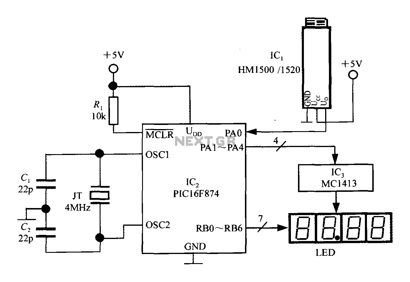
The intelligent humidity meter circuit is designed to measure and display relative humidity levels accurately. The HM1500/1520 humidity sensor (IC1) detects humidity in the environment and outputs an analog voltage proportional to the humidity level. This analog signal is fed into the PIC16F874 microcontroller (IC2), which contains an integrated 10-bit successive approximation ADC that converts the analog signal into a digital format for processing.
The microcontroller is clocked by a 4MHz oscillator, ensuring efficient operation and timely processing of the input signals. The use of capacitors (C1 and C2) stabilizes the oscillator circuit, providing a reliable clock signal for the microcontroller.
The microcontroller’s I/O ports are configured to facilitate interaction with the humidity sensor and the LED display. The PA0 pin is dedicated to reading the analog voltage from the humidity sensor, while the PA1 to PA4 pins are used to generate scanning signals that control the MC1413 inverter, which drives the common cathode LED displays. The RB0 to RB6 pins output the necessary signals to light up the corresponding segments of the 7-segment displays, allowing for clear visual representation of the humidity readings.
The PIC16F874's power management features ensure that the device remains operational within a specified voltage range. The brownout reset feature protects the microcontroller from erratic behavior during voltage drops, and the retention of RAM data during power loss enhances reliability in applications where power stability may be a concern.
Overall, this intelligent humidity meter circuit is a robust solution for monitoring humidity levels, making it suitable for various applications in environmental control, HVAC systems, and other areas where humidity measurement is critical.Intelligent humidity meter circuit by the HM1500 / 1520 humidity sensor and MCU configuration shown in Fig. The meter + 5V power supply, with four common cathode LED digital tube. CCP uses three circuit IC: IC1 to HM1500 / 1520 humidity sensor, IC2 is produced by the US microchip band (Microchip) Company 10-bit ADC of microcontroller PIC16F874, IC3 7 Darlington inverter drive array MC1413. PIC16F874 is a cost-effective 8-bit microcontrollers, containing 8 10 successive approximation A / D converter, up to 8 humidity signal analog to digital conversion, is only the way in which.
JT is 4MHz quartz crystal oscillators coupled capacitors C1, C2 can be provided after 4MHz clock frequency of the microcontroller. PIC16F874 wide supply voltage range (+ 2.5 ~ + 5V), suitable for low voltage power supply, quiescent current is less than 2mA.
RA port (RA0 ~ RA7) for the I / O interface, now use PA0 (also known AIN0) opening line to receive the voltage signal generated by the humidity sensor. PA1 ~ PA4 output bit scanning signal, bit-MC1413 obtained by inverting the drive signal. RB0 ~ RB6 output RB mouth 7-segment code signal, then the corresponding electrode segment LED display pen a ~ g.
PIC16F874 also has a power-down protection, MCLR to brownout reset latch side. When UDD from + 5V down to + 4V, the chip enters the reset state. When the power supply has returned to normal, must 72ms delay before the detachment state into normal state. Data during power failure RAM remain unchanged, will not be lost.
Related Circuits
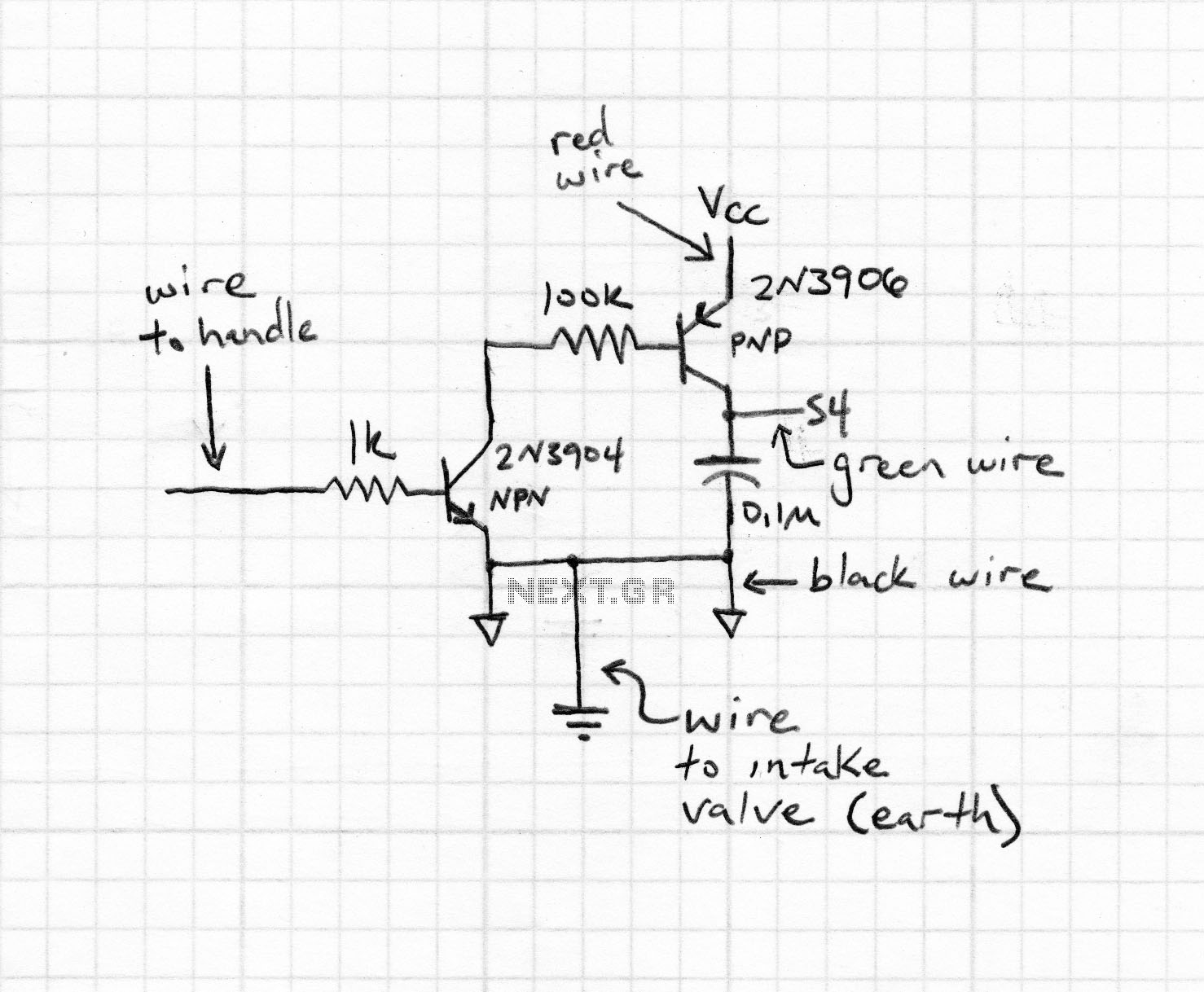
An intervalometer for the Canon 400D camera has been developed. This device is based on an Arduino platform and utilizes code adapted from the creator of the Intervaluino project. The intervalometer is a specialized electronic device designed to automate the...
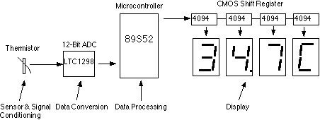
This assignment pertains to the course "Designing Microprocessor Based Instrumentation." The project features a board that utilizes a 12-bit ADC, a C program with digital filtering, and an LED display interface. It achieves a temperature reading sensitivity of 0.1°C....
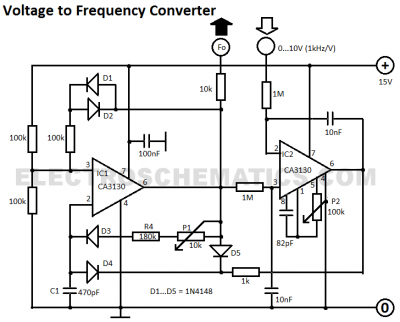
This voltage-to-frequency converter circuit features a voltage-controlled oscillator with a small deviation of 0.5%. The integrated circuit IC1 operates as a multivibrator. The voltage-to-frequency converter circuit is designed to convert an input voltage into a corresponding frequency output. The core...
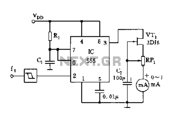
The circuit consists of a 555 timer along with components R1, C1, and other elements configured as a monostable delay circuit. The input square wave signal is shaped by a Schmitt trigger to meet the triggering requirements. The 555 timer...
This digital thermometer circuit diagram utilizes a standard 1N4148 diode as the temperature sensor. The temperature coefficient of the diode is -2 mV/°C. The digital thermometer circuit leverages the characteristics of the 1N4148 diode, which exhibits a predictable voltage drop...
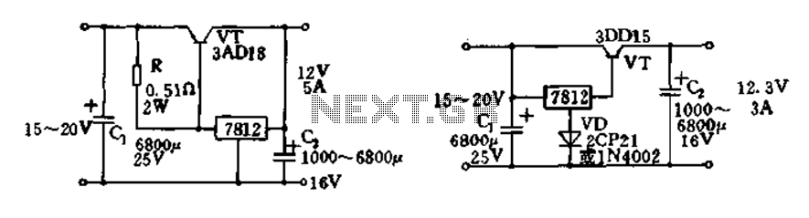
Expand integrated three-terminal regulator block circuit output current method The integrated three-terminal regulator is a versatile component commonly used in power supply circuits to provide a stable output voltage. This regulator typically consists of three terminals: input, output, and ground....
Warning: include(partials/cookie-banner.php): Failed to open stream: Permission denied in /var/www/html/nextgr/view-circuit.php on line 713
Warning: include(): Failed opening 'partials/cookie-banner.php' for inclusion (include_path='.:/usr/share/php') in /var/www/html/nextgr/view-circuit.php on line 713