
Wide-band high-frequency electric field strength meter schematic
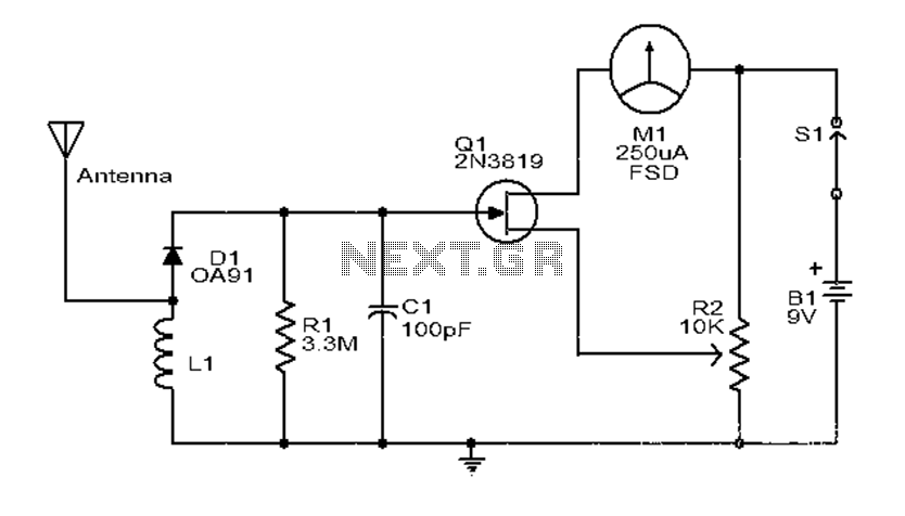
The electric field strength meter operates by detecting the electromagnetic fields generated by radio frequency (RF) signals. The core component, a coil, acts as an antenna that captures RF energy. The captured signal is then rectified by diode D1, converting the alternating current (AC) signal into a direct current (DC) voltage. This DC voltage is crucial as it is used to bias the Field Effect Transistor (FET), which amplifies the signal to a level that can be read by the meter (M1).
Calibration is a critical aspect of the design. By adjusting the preset resistor R2, the user can ensure that the meter reads zero when no signal is present, providing an accurate baseline for measurements. This feature is particularly important for ensuring the reliability of the readings, especially in environments with varying background noise.
The sensitivity of the circuit can be influenced by the choice of the meter (M1). A 250µA meter is specified, but using a meter with lower current ratings can increase the sensitivity of the device, allowing it to detect weaker signals.
The construction of the coil (L1) is also essential for the performance of the meter. The coil should be wound with care, ensuring that the 20 enameled copper wires are tightly coiled around a 6-inch plastic ring to form an efficient inductor. This design optimizes the coil's ability to capture RF signals.
The inclusion of a telescopic whip antenna further enhances the device's performance by improving its ability to receive signals from various directions. This antenna type is adjustable, allowing the user to optimize reception based on the specific frequency being measured.
In summary, this electric field strength meter is designed for simplicity and cost-effectiveness while offering the functionality needed to measure and analyze RF signals. The careful selection of components and calibration methods contributes to its effectiveness, making it a practical tool for hobbyists and professionals alike.Explanation: This is a simple and low-cost broad-band high-frequency electric field strength meters. Field strength of the radio signal into a DC measurement, it is measured. R F signal will be picked up by the coil and the diode D1.Even a very small DC voltage, enough to change the sign of the bias FET and a radio signal will be reflected in the presence of meters corrected. The instrument can be calibrated to adjust preset R2 meters M1 money supply in the absence of any radio signal reading zero.
The circuit is not very sensitive to the hand held FM transmitter from a distance of several meters (ideal theoretical demonstrations) radio signals, but can feel. Circuit diagram and parts list Precautions The circuit can be assembled in the general PCB. Use a 9V PP3 battery powered circuit. Use a 250uA meter M1.Using fire a low fire meters will increase sensitivity. Coil L1 can be on Before 6 inch plastic ring 20 enameled copper wire wound. The telescopic antenna whip antenna.
Related Circuits
This is a schematic diagram of a stereo audio amplifier for a car. The circuit is powered by a single IC, the TDA1553, along with some external components. This IC is designed to manage the stereo car audio system....
In the circuit below, a quad voltage comparator (LM339) is utilized as a simple bar graph meter to indicate the charge condition of a 12-volt lead-acid battery. A 5-volt reference voltage is connected to each of the positive inputs...
A recently discovered schematic appears to be authentic and does not include the 555 timer. Additionally, a picture of Brian Davis on this page shows him holding the etch mask, which does not exhibit any features resembling a socket...

A UJT organ circuit with a circuit diagram is explained in detail. A 2N4891 UJT is used for the operation of the circuit. The UJT (Uni-Junction Transistor) organ circuit is designed to utilize the unique characteristics of the 2N4891 UJT...
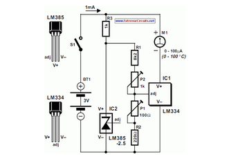
The circuit of the Celsius thermometer in the diagram is based on the well-known Type LM334 from National Semiconductor. This integrated circuit (IC) serves as a sensor that provides temperature readings. The Celsius thermometer circuit utilizes the LM334 integrated circuit,...
This chapter contains circuit diagrams for several power supplies for pulsed solid-state lasers. These include units suitable for driving the popular Hughes ruby and YAG rangefinder laser assemblies, one utilizing the flash from a disposable pocket camera, and a...