
SIMPLE TLO82 VCO

The described voltage-controlled oscillator (VCO) circuit employs the TL082, which is a low-noise JFET-input operational amplifier known for its high input impedance and low offset voltage. The VCO's output frequency is modulated by an input control voltage, allowing for precise frequency tuning across the specified range.
In this configuration, the TL082 operates in an astable multivibrator mode, where the frequency of oscillation is determined by external resistors and capacitors connected to its inverting and non-inverting inputs. The feedback network is crucial in establishing the timing characteristics of the oscillation, typically involving resistors that set the charge and discharge times of the timing capacitor.
The relationship between the control voltage and the output frequency is linear within the specified range, providing a predictable response suitable for applications such as signal generation, modulation, and frequency synthesis. The circuit may include additional components such as diodes for temperature compensation or filtering capacitors to stabilize the output signal and reduce noise.
To ensure optimal performance, careful selection of the component values is necessary, taking into account the desired frequency range and the characteristics of the TL082. Furthermore, proper power supply decoupling should be implemented to minimize noise and enhance the stability of the oscillator.
Overall, this voltage-controlled oscillator circuit is versatile and can be adapted for various applications in electronic systems requiring frequency modulation or signal generation.This circuit uses a dual operational amplifier (TL082) to form a voltage-controlled oscillator (VCO). With the component values shown, the output-frequency range is 100 Hz to 10 kHz when the input control voltage is between 0.
05 and 10 V. 🔗 External reference
Related Circuits
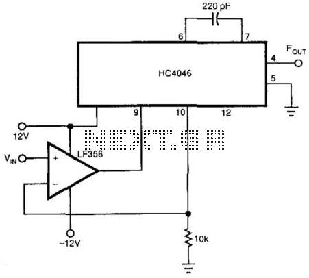
This voltage-controlled oscillator (VCO) utilizes an LF356 operational amplifier to create a linear relationship between frequency and voltage, employing the CMOS HC4046. The frequency range can be adjusted by modifying the capacitor connected between pins 6 and 7 of...
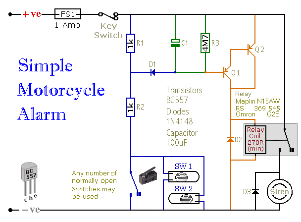
When one of the switches is closed, the base of Q1 is connected to ground through D1 and R2. This activates Q1, which in turn activates Q2. Q2 connects the positive side of the relay coil to the supply...
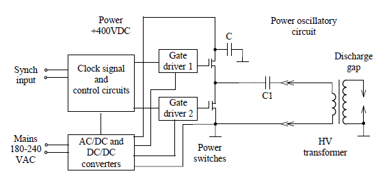
Simulate the electric field within a gas-filled discharge gap generated by a radio frequency voltage generator. The circuit, provided by the experimenters at a distance, is depicted in the accompanying image. The numerical values are as follows: C1 =...
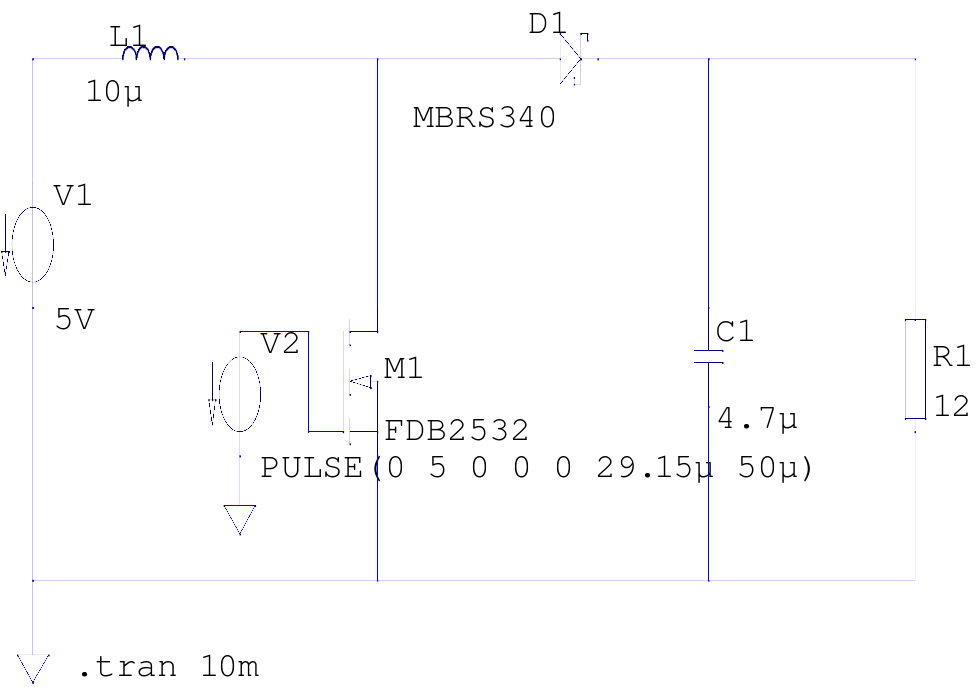
The supply voltage is 5V, and the goal is to increase it to 12V with a load current of 1A, resulting in an output power of 12W. A switching frequency of 20kHz has been selected, requiring a duty cycle...
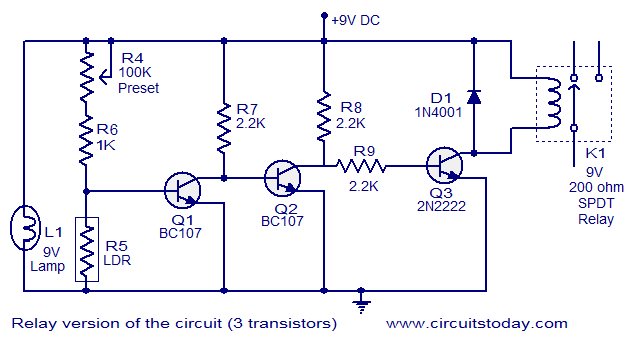
This document describes a simple fire alarm circuit utilizing a Light Dependent Resistor (LDR) and lamp combination for fire detection. The alarm activates by detecting smoke generated during a fire. When smoke is present, the circuit triggers an audible...
This simple circuit allows the use of an oscilloscope as a Time Domain Reflectometer (TDR). The operation involves sending a pulse down a cable and observing the resulting reflections. The circuit design for utilizing an oscilloscope as a Time Domain...