
power supply Why is my simple boost converter giving me such a high peak output voltage
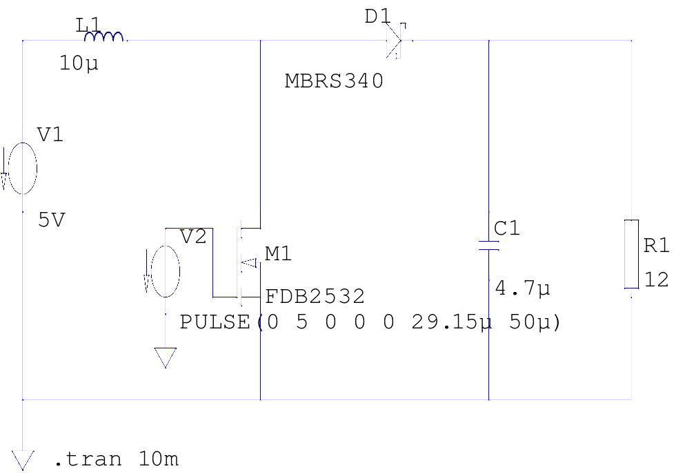
The circuit described is a DC-DC boost converter designed to step up a 5V supply voltage to 12V while delivering a load current of 1A. The converter operates under a switching frequency of 20kHz initially, with a calculated duty cycle of approximately 58.3%, indicating the duration the switch (NMOS transistor) remains on during each cycle. The theoretical on-time of 29.15 µs is critical for achieving the desired output voltage and current.
The input power is calculated based on the efficiency of the converter, which is assumed to be 90%. This results in an input power requirement of 13.34W, leading to an input current of 2.67A. The circuit design anticipates specific voltage levels at two measurement points: point 2, located between the inductor and the NMOS, is expected to show a steady 5V with slight ripple, while point 3, situated between the diode and the output capacitor, should stabilize at 12V with some ripple.
The initial results, however, indicate unexpected behavior, with point 2 showing a peak voltage of 23V and point 3 displaying a peak of over 22.5V. This chaotic output suggests potential issues with the switching frequency or component values. The adjustment of the switching frequency to 200kHz resulted in improved performance, aligning closer to the expected output voltages at both points, albeit with still significant ripple.
The inductor's value was increased to 100 µH in an attempt to stabilize the output, but this change primarily affected startup characteristics without significantly reducing the ripple. A more effective modification was the increase in output capacitance to 10 µF, which effectively minimized the voltage oscillation at point 3, demonstrating the importance of capacitor sizing in filtering output ripple in switching converters.
In summary, the circuit's performance reflects the complexities of switching power supplies, where component selection and operating frequency play crucial roles in achieving stable and efficient voltage conversion. Further refinement of the design may involve optimizing the inductor and capacitor values, as well as fine-tuning the switching frequency to minimize ripple and stabilize output voltages.The supply voltage is 5V and I am seeking to increase it to 12V with a load current of 1A, or an output power of 12W. I selected a switching frequency of 20kHz. By my math, I need a duty cycle of 0. 583 to do this, so the on time should be 29. 15 µs. Assuming an efficiency of 0. 90, the input power will be 13. 34W and the input current 2. 67A. What I expected to see is a voltage of 5V, perhaps with a slight ripple, at point 2 (between the inductor and the NMOS) and a voltage of 12V with a ripple at point 3 (between the diode and the capacitor). Instead, what comes out is what looks like total chaos - I get a peak voltage of 23V that oscillates around 11.
5V at point 2 and a slightly lower peak voltage of just over 22. 5V that oscillates around 17V at point 3: On the hunch that my switching frequency might be too low, I tried increasing it to 200kHz (T=5 µs, Ton=2. 915 µs) and now I get something more like what I was looking for, which is a peak voltage of 12. 8V at point 2 (oscillating between that and 0V) and a peak of 12V at point 3 (oscillating about 11. 8V): There was significant ripple in the voltage. I tried increasing the size of the inductor to 100 µH but all it seemed to affect was the startup oscillation.
So I increased the capacitance to 10 µF, and that seemed to work, the voltage oscillation at point 3 is much smaller. The image above is the result with a 10 µF capacitor. 🔗 External reference
Related Circuits
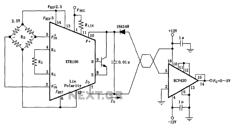
The IN4148 series diode is connected in the V+ line and configured in a loop to prevent damage from reverse voltage conditions. The diode exhibits a forward voltage drop of approximately 0.7V, which affects the supply voltage. The circuit...
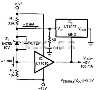
A method for enhancing the output current of a reference while also providing overload protection is illustrated. In this configuration, IC1 functions as a power buffer. The LT1027 regulates the output voltage (Vout) and ground to maintain a stable...
Here is something that may interest crystal radio builders: a one-transistor (silicon) AM broadcast receiver that derives its power from ambient AC hum and static. The schematic is adapted from Darryl Boyd's "Stay Tuned" website, which features over 170...
This voltage-controlled frequency divider circuit produces lower frequency pulses that depend on the control voltage, with synchronous rising edges for the input and output pulses. Typically, such frequency dividers utilize a monostable circuit connected between an inverted output and...
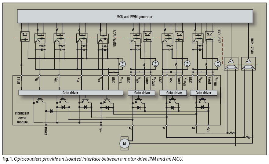
An interface circuit utilizing optocouplers provides galvanic isolation and common-mode noise rejection between low-voltage microcontroller units and high-voltage integrated power modules in motor-drive applications. Optocouplers ensure high-voltage isolation between a low-voltage device, such as a microcontroller or a pulse-width...
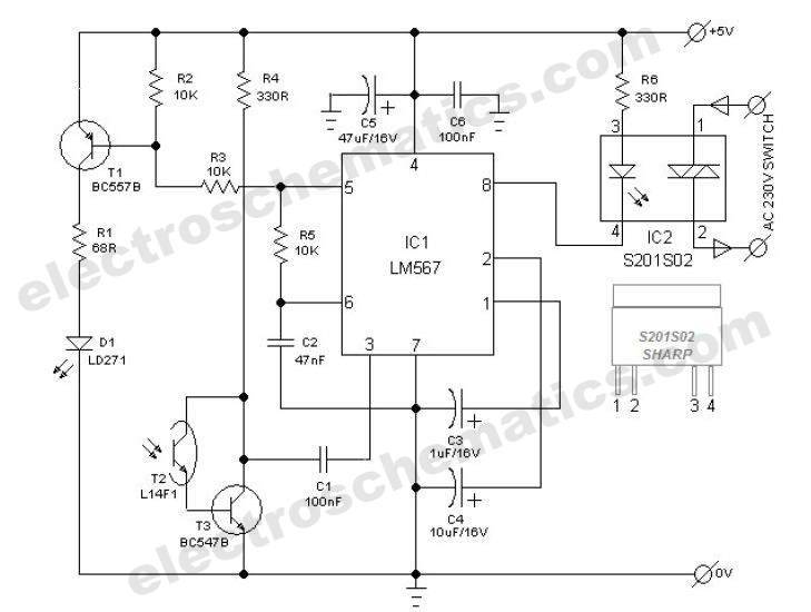
The power switch with an infrared proximity sensor is designed to detect obstructions at distances ranging from a few millimeters to several centimeters. The power switch utilizing an infrared proximity sensor operates on the principle of emitting infrared light and...
Warning: include(partials/cookie-banner.php): Failed to open stream: Permission denied in /var/www/html/nextgr/view-circuit.php on line 713
Warning: include(): Failed opening 'partials/cookie-banner.php' for inclusion (include_path='.:/usr/share/php') in /var/www/html/nextgr/view-circuit.php on line 713